Shinan-Ui OW · Project Risk Tracker & OI Support · by Luca Montalti & Angelo Vallozzi
Access Required
Dynamic project risk tracker — restricted to authorised users. Enter the password to continue.
🚧Work in Progress — Tool under active development, modifications and improvements may be added at any time|Always verify results independently before engineering use🚧
Shinan-Ui OW · by Luca Montalti & Angelo Vallozzi
Project Risk Tracker & OI Support
Offshore wind foundation T&I risk management — installation risk maps and offshore calculation tools.
PROJECT
📋
Shinan-Ui OW External Project Risk Tracker & OI Support
Project risk registers, action trackers, installation progress monitoring, drivability & settlement risk maps, refusal mitigation measures and T&I management tools for the Shinan-Ui Offshore Wind project.
Open Project Tracker →
CALCULATIONS
⚓
Offshore Foundation Calculation Tool
A growing toolset for foundation & T&I engineers — spudcan penetration, pile design, rigging, grillage, seafastening, transportation loads and more.
Open Calculation Tool →
Offshore Calculations · by Luca Montalti & Angelo Vallozzi
Offshore Foundation Calculation Tool
Calculation tools for offshore foundation engineers.
SNAME T&R 5-5AISO 19905-1ISO 19901-4DNV-ST-N001DNV-ST-0126DNV-ST-F101DNV-RP-C203API RP 2GEOAPI RP 2AXie et al. (2010)Meyerhof & HannaSkempton (1951)DNV-RP-0618Sumer & Fredsoe (2002)Soulsby (1997)
Foundation Calculations
Select a tool to begin your analysis
⛶
Spudcan Penetration – LPA
Leg Penetration Assessment for jack-up rigs. Calculates penetration resistance profiles using the Xie et al. multilayer algorithm with punch-through and squeezing failure modes.
MultilayerPunch-ThroughSqueezingSand & Clay
⬆
Leg Extraction Assessment – LEA
Spudcan extraction force prediction using Purwana et al. (2010). Calculates required pull-out load accounting for backfill resistance, reverse end bearing and jetting effects. Integrated within the LPA tool as Step 5.
Purwana 2010Extraction ForceSuctionClay
🔩
Pile Drivability – SRD
Soil Resistance to Driving (SRD) using Alm & Hamre (2001) CPT-based method for cohesive, non-cohesive, glauconite and rock soils. Friction fatigue and GRLWEAP input generation.
Alm & HamreSRDCPT-basedGRLWEAP
⚠
Pile Run Risk Assessment
Pile run (dropfall) risk screening based on ISFOG2025-516. DNV (1992) & Alm & Hamre (2001) SRD methods with Sun et al. (2022) energy equation for pile run velocity prediction. AGS input supported.
ISFOG2025DNV / A&HPile RunAGS Input
▭
Mudmat / Shallow Foundation
Undrained bearing capacity, penetration resistance, settlement analysis for mudmats and skirted shallow foundations per DNV-RP-C212, ISO 19901-4 and SNAME.
SkemptonHansenDNV & ISOSettlement
📈
CPT Interpretation
Import AGS CPT data, plot qc, fs, u2, Rf profiles, and derive cu, φ', unit weight, Vs, G0, moduli, K0, OCR, relative density, sensitivity and liquefaction assessment using Robertson (2009), Mayne (2023) and more.
AGS ImportRobertson 2009Mayne 202317+ Parameters
⚙
Pile Tip Buckling & Integrity Check
Casing/pile tip buckling propagation screening (Aldridge et al. 2005), driving stress overstressing analysis, and minimum wall thickness assessment for driving into rock. For offshore monopiles and casing installation.
In-place axial pile capacity (shaft friction + end bearing) using 5 methods: API traditional, ICP-05, UWA-05, Fugro-05 and NGI-05. Supports sand, clay, and layered soils. Manual strata input or AGS file import. Includes API p-y curves, t-z/Q-z load transfer, and method comparison.
API RP 2GEOICP-05UWA-05Fugro-05NGI-05p-y CurvesAGS Import
API RP 2GEODNV-RP-C212Bearing CapacityVHM EnvelopeSlidingSettlement
WIP
📈
Settlements Analysis
Consolidation and immediate settlement calculations for shallow foundations on clay. Oedometer-based 1D consolidation with Terzaghi and Biot consolidation theories.
ConsolidationTerzaghiOedometer
WIP
△
Shallow Foundation Bearing Capacity
General bearing capacity for shallow foundations using Meyerhof, Vesic and Hansen methods. Includes shape, depth, inclination and eccentricity factors.
MeyerhofHansenVesic
WIP
▲
Pile Design – Axial Capacity
API RP 2GEO / ISO 19901-4 pile axial capacity calculations for offshore driven piles. Skin friction and end bearing for clay (alpha method) and sand (beta method).
P-Y curve derivation and lateral pile response. API soft clay (Matlock), stiff clay (Reese) and sand (Reese) formulations with PISA monopile extensions.
API RP 2GEOP-Y CurvesMonopilePISA
WIP
▮
Monopile Sizing & Design
Preliminary and detailed monopile design for offshore wind foundations. Covers diameter and wall thickness sizing, lateral capacity via P-Y curves (API / PISA), natural frequency check (1P–3P range), driving feasibility and fatigue screening per DNV-ST-0126 and ISO 19901-4.
DNV-ST-0126P-Y / PISANatural FrequencyDrivability
WIP
📈
Liquefaction Screening – CPT
CPT-based liquefaction susceptibility using Robertson & Wride (1998) and Boulanger & Idriss (2014). Factor of safety profile and liquefied layer identification.
Axial and lateral friction, embedment and on-bottom stability for subsea pipelines and cables. Covers DNV-ST-F101 and AGA methodologies.
DNV-ST-F101EmbedmentOn-Bottom StabilityFriction
WIP
🧪
Soil Index Properties
Correlation toolkit for soil classification and index properties. Converts between Atterberg limits, plasticity index, liquidity index, unit weight and void ratio. Includes Casagrande plasticity chart and USCS/BS soil classification.
Offshore T&I calculations — lifting, seafastening, transportation and marine operations · Based on DNV-ST-N001
🏗️
4-Point Rigging Design
Heavy lift rigging design calculator for 4-point padeye lifts. Computes sling design loads (SDL), sling & shackle unity checks, skew load factors per DNV-OS-H205, tilt analysis, and Centre of Hook geometry with full rigging visualisation.
DNV-OS-H205Sling SDLSkew LoadTilt Analysis
WIP
🔩
Lifting Point Design & Check
Structural verification of padeyes and trunnions: load distribution per lifting point, tilt calculations, sling/shackle CRBL verification with bending & termination reduction factors, weld capacity check.
PadeyeTrunnionCRBLSling Loads
WIP
🚢
Transportation Loads
Motion-induced acceleration and load calculation on cargo during sea transport. Vertical, horizontal and uplift loads from vessel pitch, roll and heave. Supports default motion criteria and AQWA-based motion analysis inputs.
DNV-ST-N001AccelerationsMotion AnalysisSea Transport
WIP
⚓
Grillage & Seafastening Design
Structural design and FEA verification of grillage (vertical load transfer) and seafastening (horizontal & uplift restraint) systems. Stopper blocks, clamps, bearing plates and interface loads to vessel deck under ULS transport loads.
GrillageSeafasteningULSFEA Verification
WIP
🔥
Weld Capacity & Fatigue Check
Fillet and butt weld strength verification under static and fatigue loading. Effective throat calculation, weld stress resultants (direct shear, bending), utilisation ratios and fatigue damage accumulation during transport and lifting.
Fillet WeldFatigueDNV-RP-C203Utilisation
WIP
🎯
Guides & Bumpers Design
Design of installation aids — stabbing guides, lead-in bumpers and guide frames for accurate offshore positioning of foundations and transition pieces. Contact load calculations, structural check of guide posts and deflection limits.
Stabbing GuidesBumpersContact LoadsPositioning
WIP
⚖️
Vessel Stability & Ballast Plan
Draft, trim and heel optimisation for cargo vessel loading. Intact and damaged stability verification, GM calculation, ballast sequence planning and freeboard checks during loadout, transit and lifting operations.
StabilityBallastGM CalculationDamage Stability
WIP
📦
Weight Control & CoG Report
Systematic weight tracking with contingency factors (P50/P95), centre of gravity envelope analysis and CoG shift under ballast changes. Feeds directly into lift plan, grillage and seafastening design load calculations.
Weight EstimateCoG EnvelopeP50 / P95Contingency
WIP
🌊
Workability Assessment
Operability analysis for offshore lifting and installation operations. Hs–Tp combined sea state limits, wave scatter diagram processing, time-of-year weather windows and percentage workability calculation against limiting criteria.
Full rigging configuration design: sling geometry (1×/2×/4× arrangements), sling angle effects, shackle selection, spreader bar structural check, and nominal safety factor verification against CRBL for wire and fibre slings.
Sling GeometryShacklesSpreader BarSafety Factors
WIP
⛵
Vessel Mooring & Bollard Pull
Mooring line load analysis for HLV at installation site and transport barge at quay. Anchor holding capacity, catenary line tensions, tug bollard pull requirements and DP capability assessment under wind, wave and current loading.
HLV MooringBollard PullCatenaryDP Capability
WIP
📋
T&I Procedure & Manual Builder
Structured template generator for Transport & Installation Manuals, task plans and offshore checklists. Covers loadout, transportation, pre-installation survey, lifting, setting, levelling, grouting and completion procedures.
T&I ManualTask PlansChecklistsDNV-ST-N001
WIP
🏗️
Crane Vessel Selection Aid
Preliminary crane vessel screening tool based on lift weight, radius, hook height and site water depth. Compares against a vessel database and identifies candidate HLVs and semi-submersibles for offshore installation campaigns.
HLV ScreeningLift RadiusDNV-ST-N001
WIP
📡
Dynamic Amplification Factor
Calculation of DAF for offshore lifts per DNV-ST-N001 and DNVGL-RP-N103. Accounts for vessel motion RAOs, crane tip dynamics, sling stiffness and splash zone crossing loads for subsea and surface lifts.
DAFDNV-ST-N001Splash Zone
WIP
🚢
Load-Out Assessment
Structural and stability assessment for quayside and float-on/roll-on load-out operations. Checks quay bearing pressure, vessel trim and heel, tipping stability, skidding forces and barge vetting criteria per DNV-ST-N001.
Roll-on / Float-onQuay BearingStability Check
Documentation & Reference Material
Presentations, technical references, design codes and training material — click to browse the library
📽️
Presentations & Workshops
Engineering session presentations, training workshops and technical seminars. Includes OWF foundation & T&I sessions, LPA/LEA methodology overviews and design approach summaries.
PresentationsWorkshopsSessions
📚
Technical References & Papers
Research papers, technical notes and methodology references covering bearing capacity theory, multilayer algorithms, punch-through mechanisms, spudcan-soil interaction and offshore geotechnical design methods.
PapersReferencesTheory
Shinan-Ui OW · by Luca Montalti & Angelo Vallozzi
Project Risk Tracker & OI Support
Risk registers, action tracking, drivability & settlement risk maps, refusal mitigation, and installation progress monitoring for the Shinan-Ui Offshore Wind project — Pin Piles & Jacket T&I.
Location-by-location installation work summaries — key parameters, driving stages, soil profiles, installation notes, risk assessment and mitigation measures for each WTG.
Per LocationInstallation NotesRisk SummaryDRAFT
🔩
Proposed Pile Driving Refusal Criteria
Location-by-location refusal blow count criteria based on rock head levels, hammer energy limits, and pile tip conditions. 27 locations — 17 into rock, 10 not into rock.
27 LocationsMENCK 1900 KJRev 02
📑
Risk Register — Pin Piles & Jacket T&I
Full risk register with 34 pile risks + 4 jacket risks. Filter by criticality (Critical, High, Medium, Low), search, and view mitigations. Source: internal HESI tracker.
5 Critical20 High10 Medium38 Total
⚠
Rock UCS & Pile Tip Refusal Risk
Unconfined Compressive Strength at pile tip level (±2m). Tip force vs refusal threshold analysis with UCS profiles for all 30 locations. Identifies where hard rock may cause early refusal.
14 High Risk3 Moderate12 Low Risk
🏙
Wind Farm Map — Installation Risks
Interactive map of the Shinan-Ui wind farm showing drivability risk classification for all 26 WTG + OSS locations.
Interactive Map26 WTG + OSS
🛠
Early Refusal Mitigation
Contingency scenarios, decision flowcharts, and mitigation process for pile driving refusal events during offshore installation.
FlowchartsContingencyDecision Process
📈
PIF Settlement Risk Map
Pile-in-frame settlement analysis at 1, 3, and 7 days. Lower and upper bound estimates with sinkage risk classification for each location.
Settlement1/3/7 DaysLB/UB
⛏
Drilled Rock Socket Stability
Open (unsupported) rock socket stability between driven pile tip and insert pile tip. 10 methods applied (RMR, Q, GSI/Hoek-Brown, Kirsch, N', SI, RMi, Critical Span, Plastic Zone, Sakurai). 19 locations analysed with per-layer detail.
6 Low5 Med-Low5 Med1 Med-High
💧
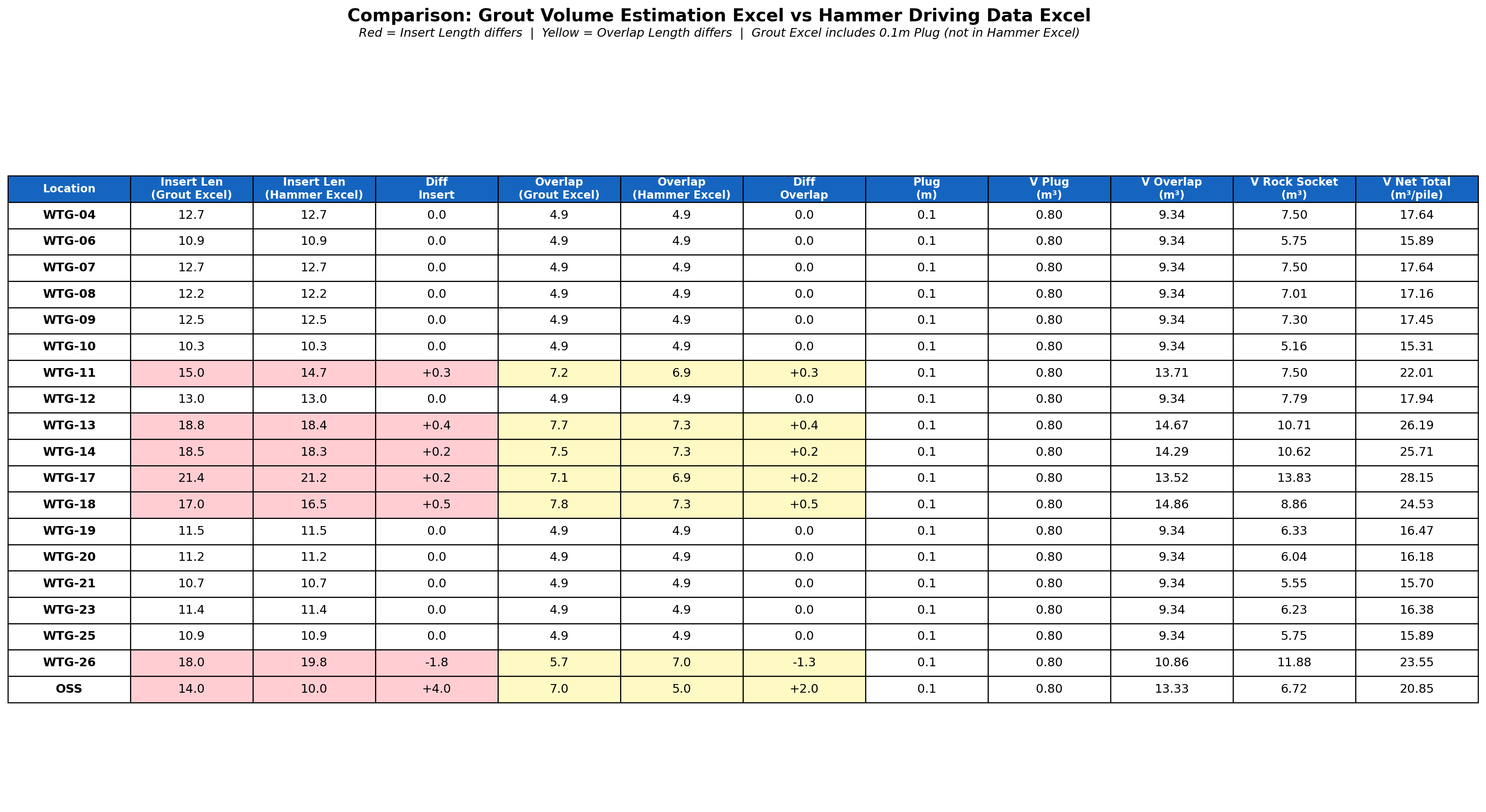
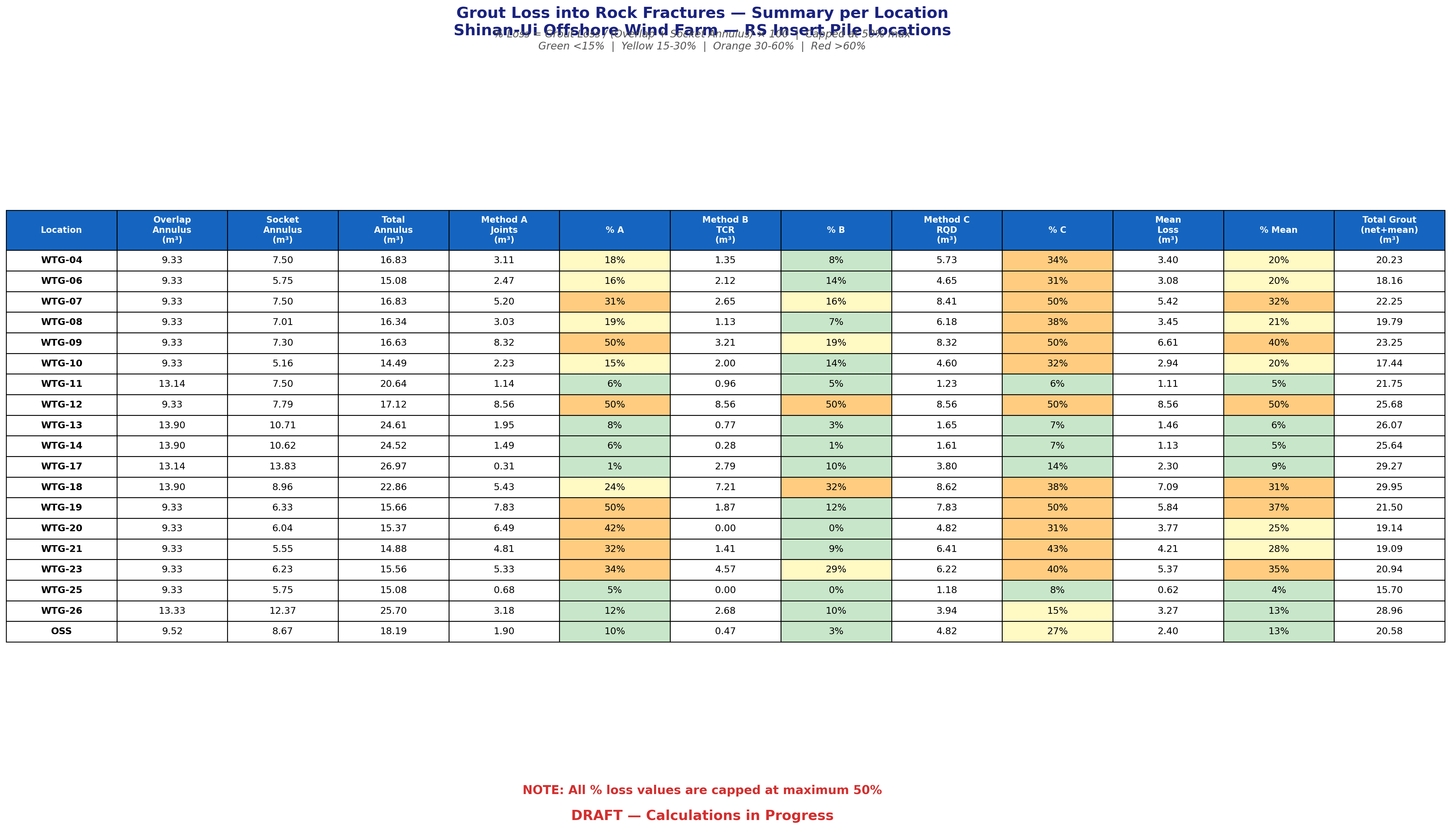
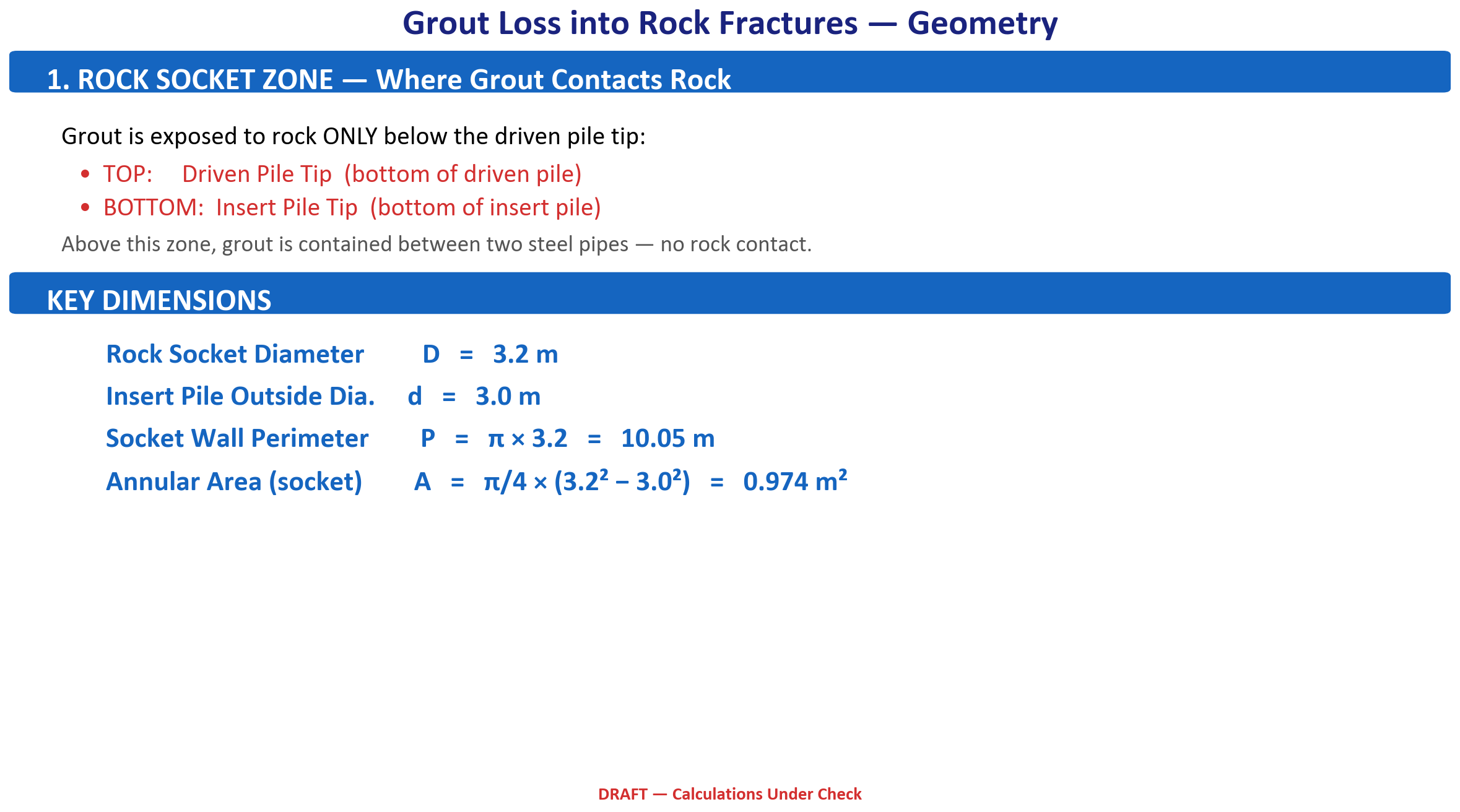
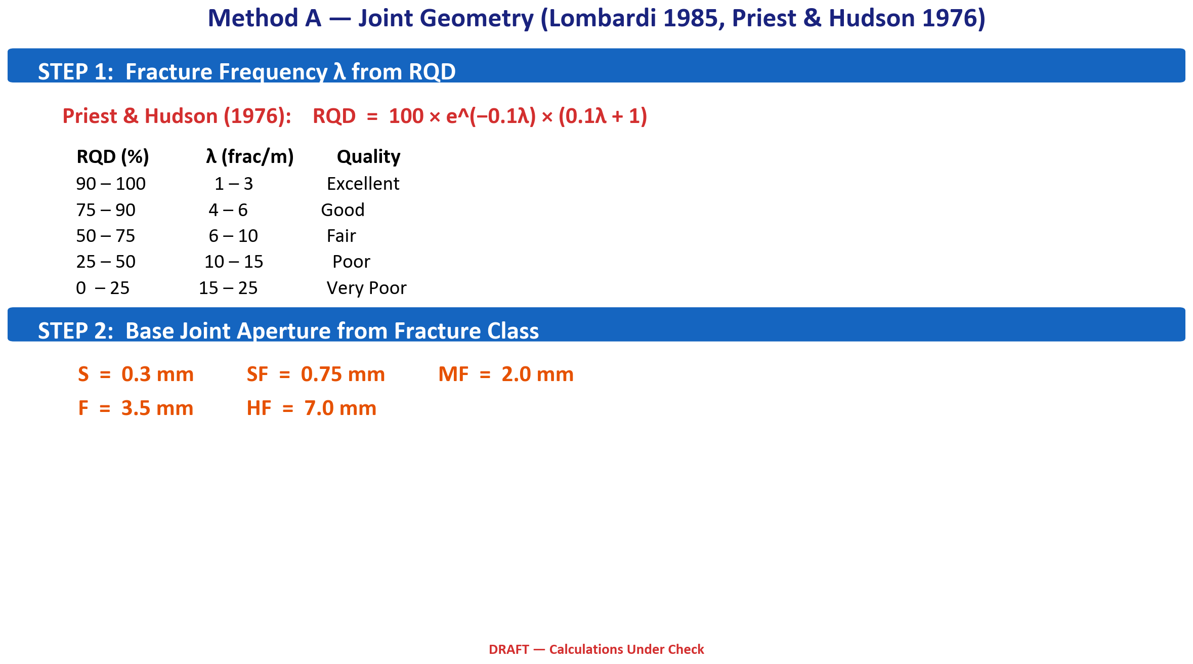
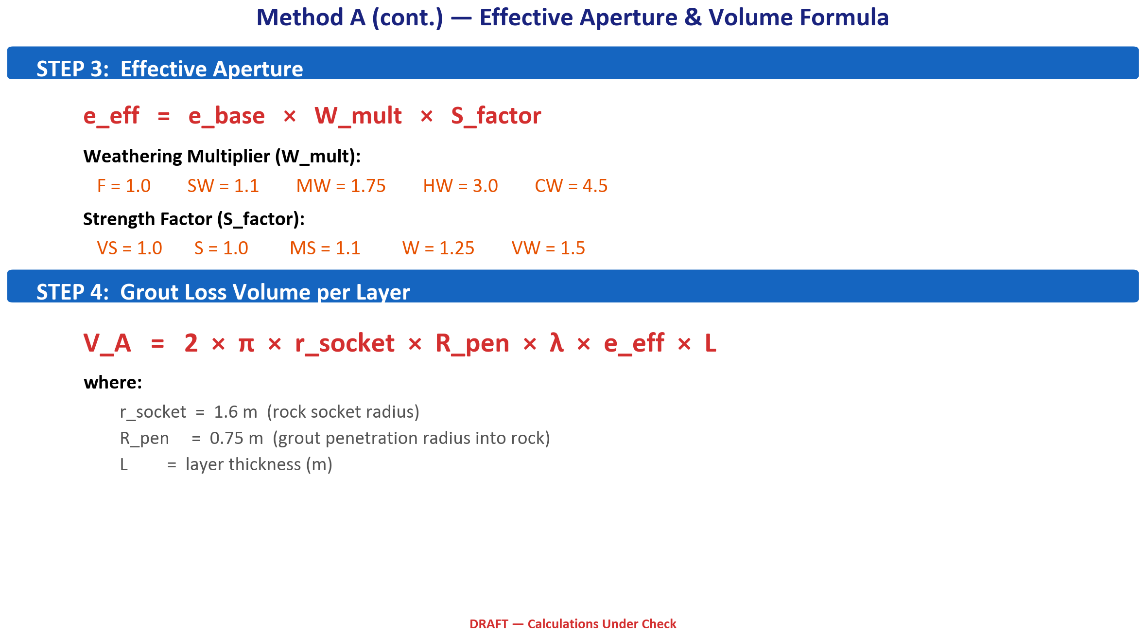
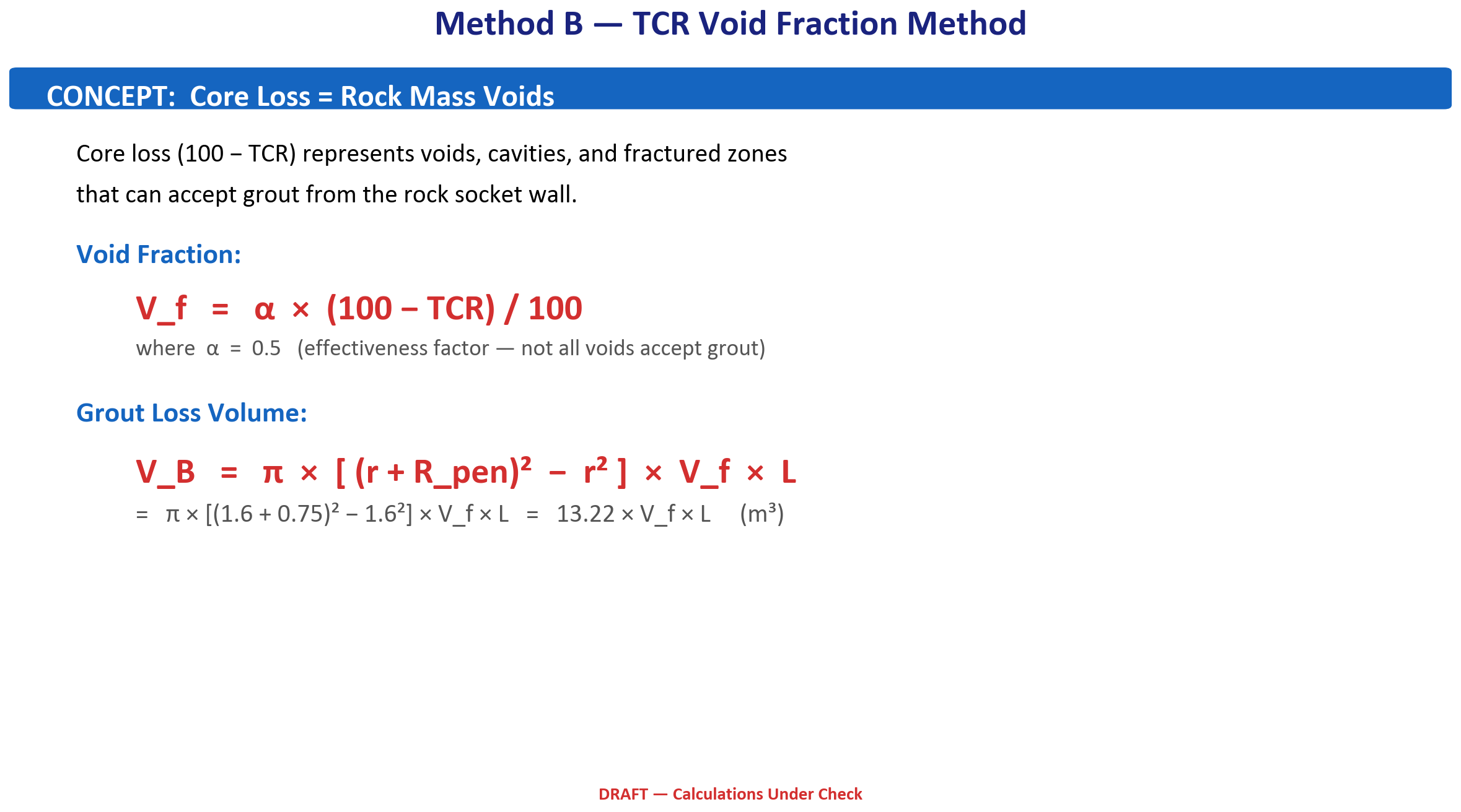
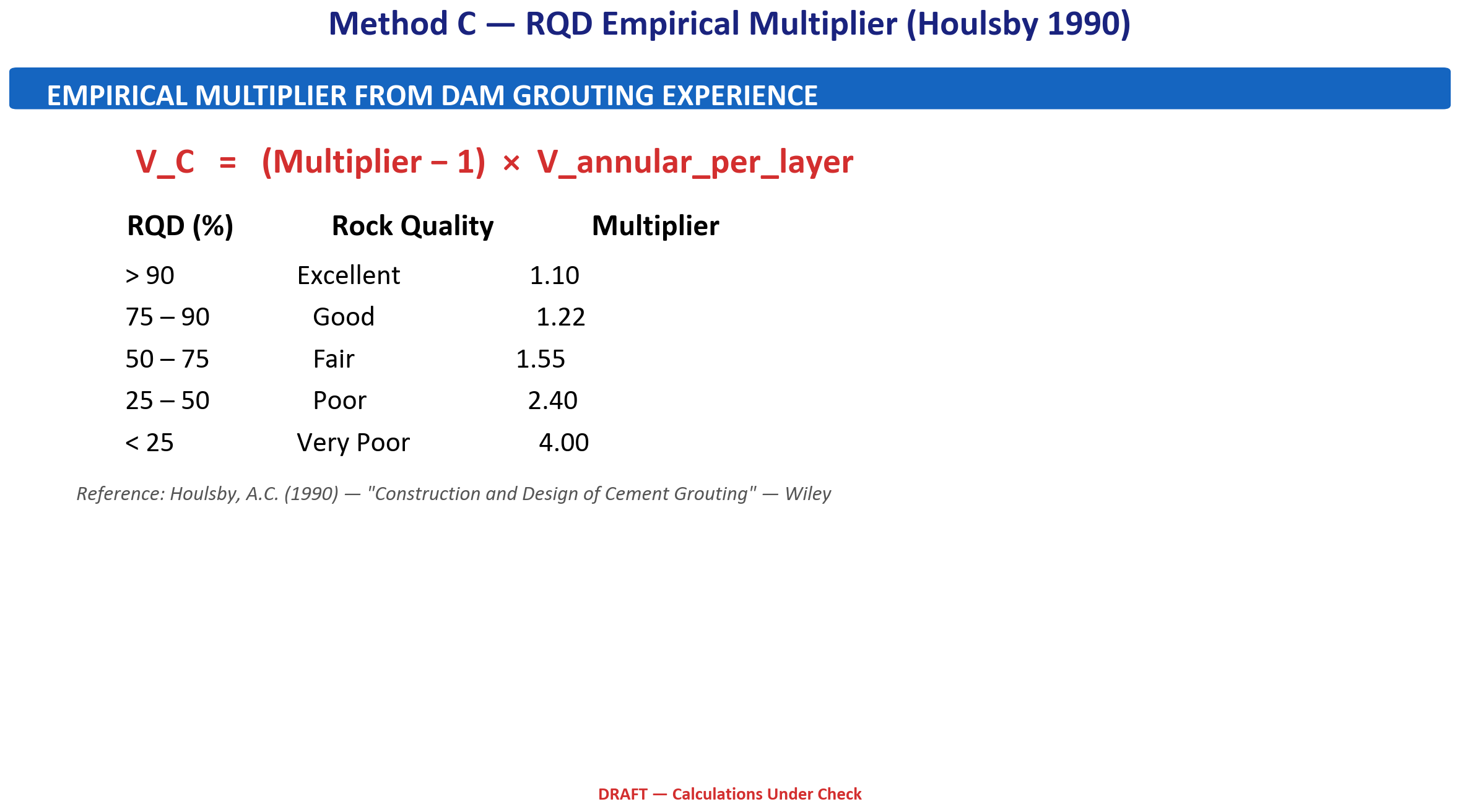
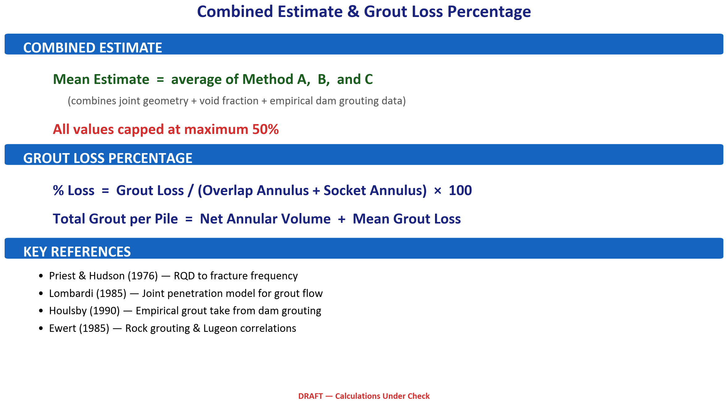
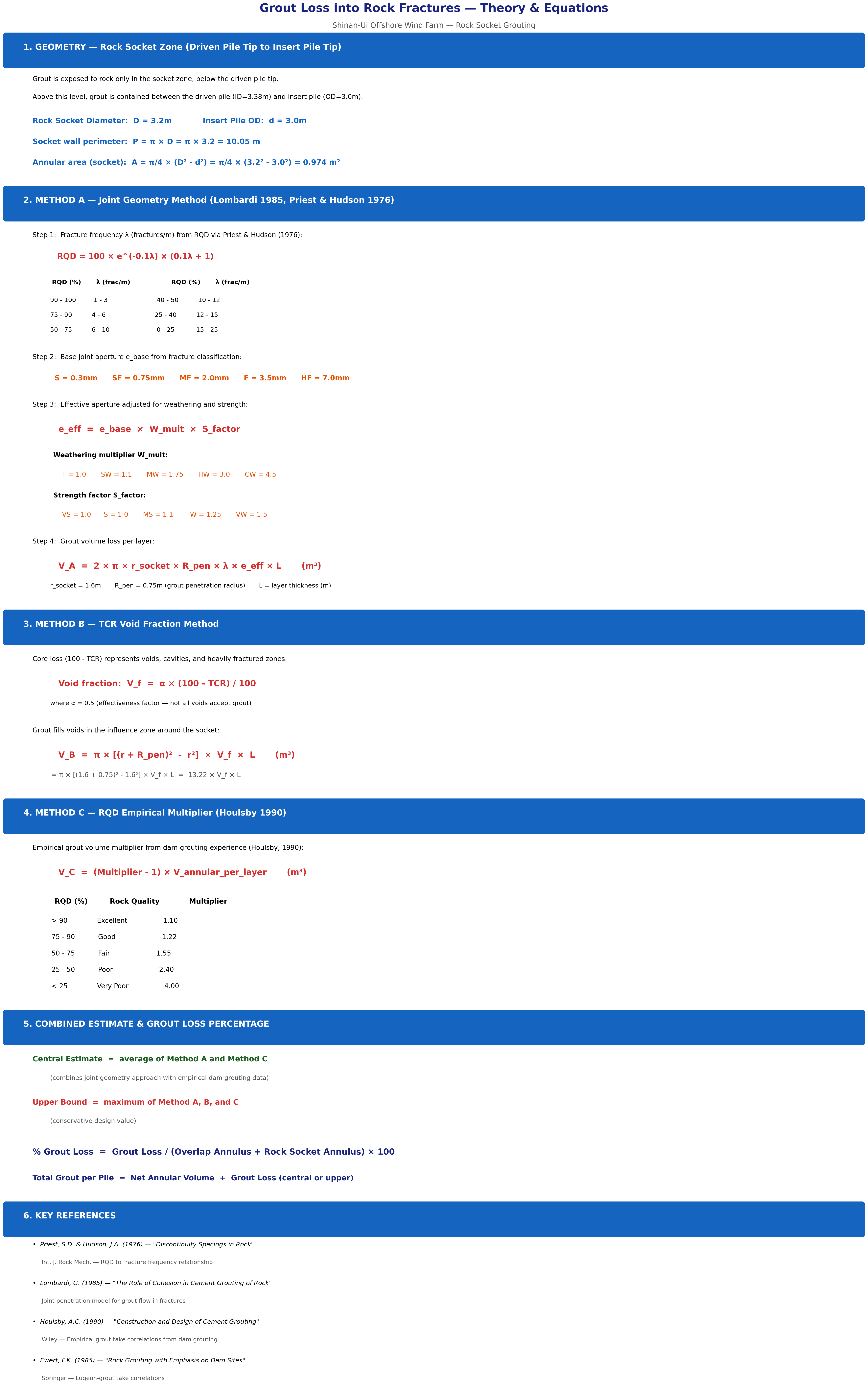
Grout Volume Loss Estimation
Grout volume calculation for rock socket grouting per WTG — plug, annulus, overlap, pipe/hose losses, and 30% overflow contingency. 18 locations, 4 piles per WTG, based on rev4 calculation (13-Mar-2026).
18 WTGsD=3.2 m socket25% contingency
⚡
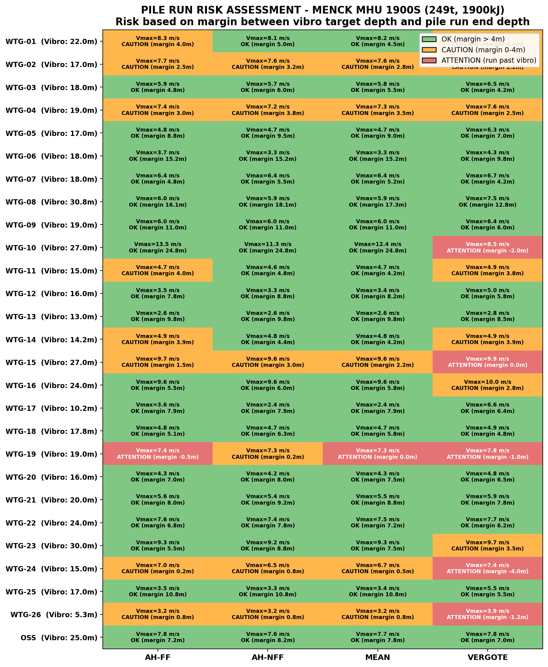
Pile Run Risk Assessment
Pile run (dropfall) screening for all 27 locations using 4 SRD methods (Alm & Hamre ± friction fatigue, MEAN, Vergote rate-dependent). Identifies where hammer placement may cause uncontrolled penetration. Based on MENCK MHU 1900S.
Pile driven into ROCK — Refusal: 100 bl/0.25m at 80% max energy
Pile NOT driven into rock — Refusal: 250 bl/0.25m continuous (see Note 2)
NOTES:
1. For piles driven into rock: primary refusal = 100 bl/0.25m at 80% of max hammer energy (80% × 1900 KJ = 1520 KJ).
2. For locations where rock head level is close below pile tip, same refusal as locations driven into rock may be applicable (100 bl/0.25m) when pile is already at deep penetration and shallow rock may be encountered.
3. If pile tip is within 1.0m of design target penetration, 250 bl/0.25m (continuous driving) may be applied to reach target depth.
4. Hammer energy shall start at a low energy level and be gradually increased as required up to a maximum of 80% of rated energy (1520 KJ). The energy ramp-up shall be managed to control pile stresses and driving response.
A 90% hammer energy may also be adopted on a location-specific basis and subject to prior discussion with the onshore engineering team.
5. Blow count limits may be reduced at specific locations based on pile fatigue and buckling analysis results (currently in progress for 1900 KJ hammer).
6. Due to lateral variability of rock head level and rock strength across the site, unexpected shallow rock head may be present at locations where no borehole data is available.
Rock head levels are based on the GIR from COWI and relate to the WR (Weathered Rock) level as included in the GIR at each location.
7. Based on location-specific pile fatigue and buckling checks, additional operational blow count limits from the contractor as per document “HESI Hammer Rental Contract_Final_duly signed_72 (Blowcount Limits)” may also be considered on a case-by-case basis.
mbsb = metres below seabed.
Risk Register — Pin Piles & Jacket T&I
Source: [INTERNAL TRACKER] Shinan UI - RISK REGISTER - Pin Piles T&I | INTERNAL — NOT FOR DISTRIBUTION
5
Critical
20
High
10
Medium
35
Open
34+4
Total (Pile+Jacket)
Filter:
ID
Criticality
Status
Category
Risk Title
Description
Owner
Proposed Mitigations
Residual
✅ Important — Expected Scenario: No Refusal
Based on COWI geophysical survey results, the pile tip at design embedment is expected to remain above the rock head level at all locations. Under this baseline scenario, no early refusal due to rock is anticipated.
The assessment below considers the unlikely contingency scenario where the actual rock head is encountered at a shallower depth than predicted by COWI — i.e., if the pile tip were to meet rock at or near the design tip level. These are extreme screening scenarios only, intended to identify which locations would be most sensitive if rock head deviates from the geophysical predictions. They do not represent expected conditions.
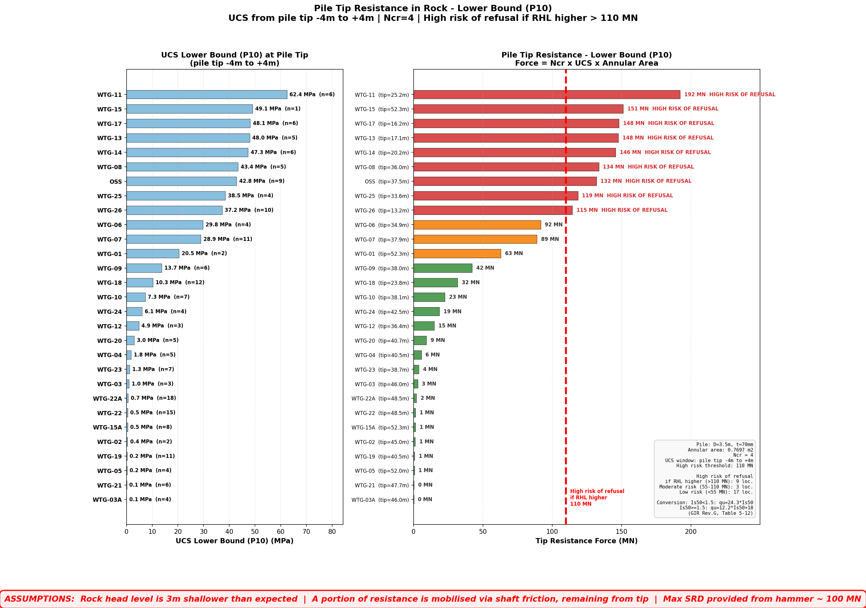
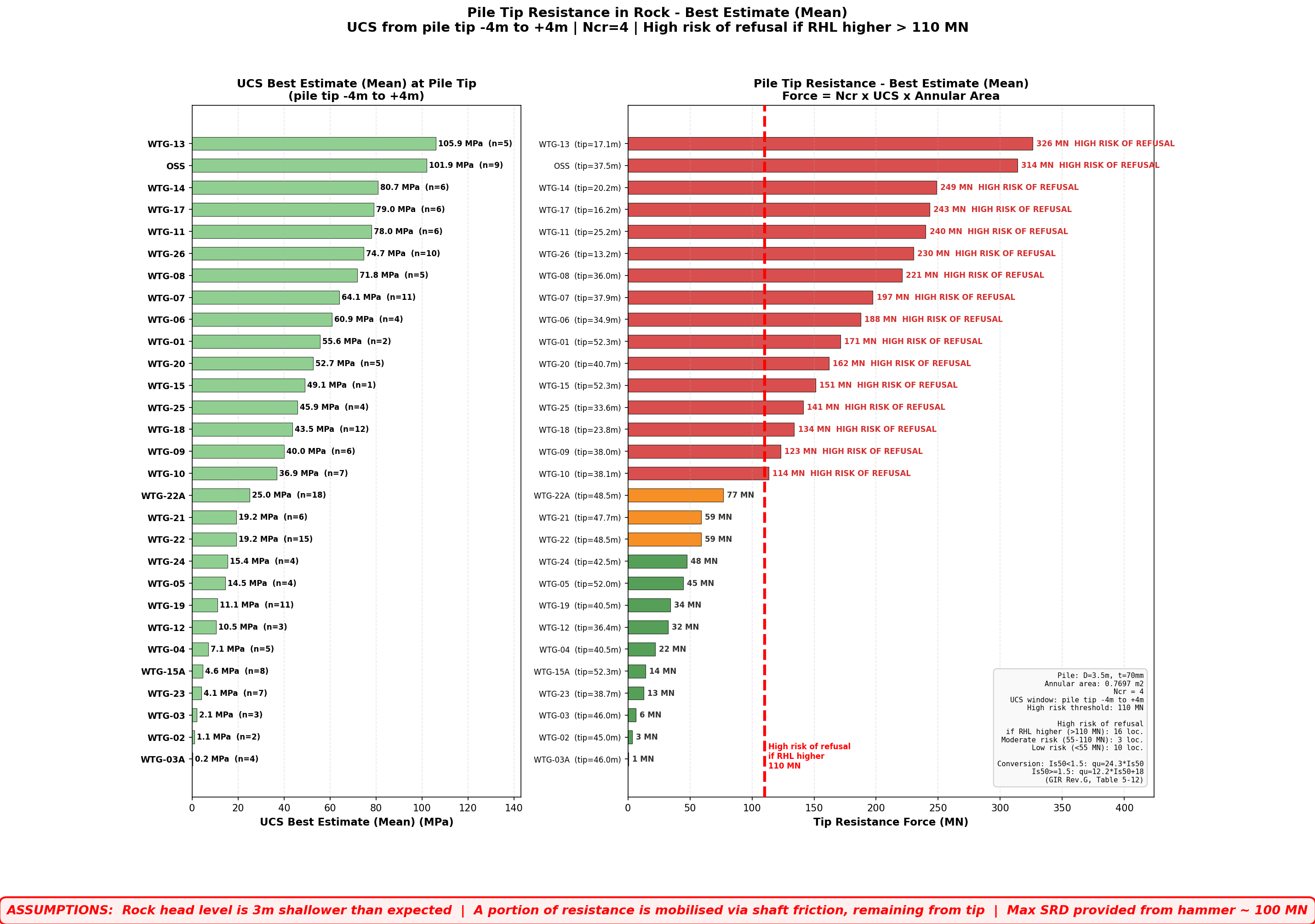
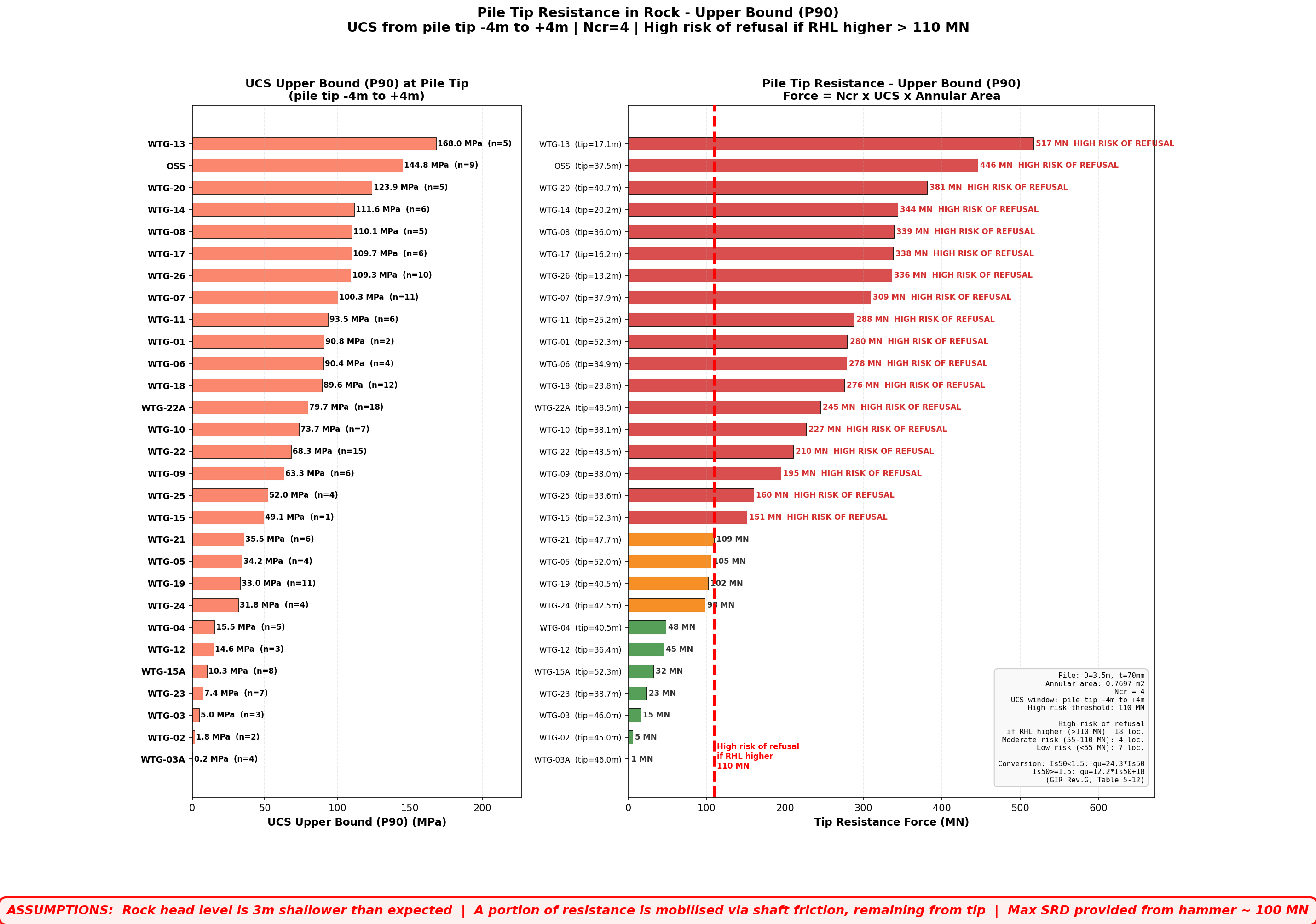
Rock UCS & Pile Tip Refusal Risk Assessment
Unconfined Compressive Strength (UCS) at pile tip level — identifying locations where hard rock units are close to the pile tip and may cause early refusal
D = 3.5m | t = 70mm | Annular area = 0.7697 m² | Ncr = 4 | Refusal threshold = 110 MN
14
HIGH RISK (BE)
3
MODERATE (BE)
12
LOW RISK (BE)
1
NO DATA
30
TOTAL LOCATIONS
Pile Tip Resistance Summary — LB / BE / UB
Lower Bound (P10)
Best Estimate (Mean)
Upper Bound (P90)
Click any image to zoom. Tip Force = UCS × Ncr × Aannular — Refusal threshold at 110 MN (red dashed line)
Filter:
Location
Pile Tip (m bsb)
N Data
UCS LB P10 (MPa)
UCS BE Mean (MPa)
UCS UB P90 (MPa)
Tip Force BE (MN)
Risk LB
Risk BE
Risk UB
UCS Plot
UCS Profiles at Pile Tip Level — All Locations
UCS data from ±2m around pile tip elevation. Click any image to enlarge. Red = high risk, orange = moderate, green = low risk.
×
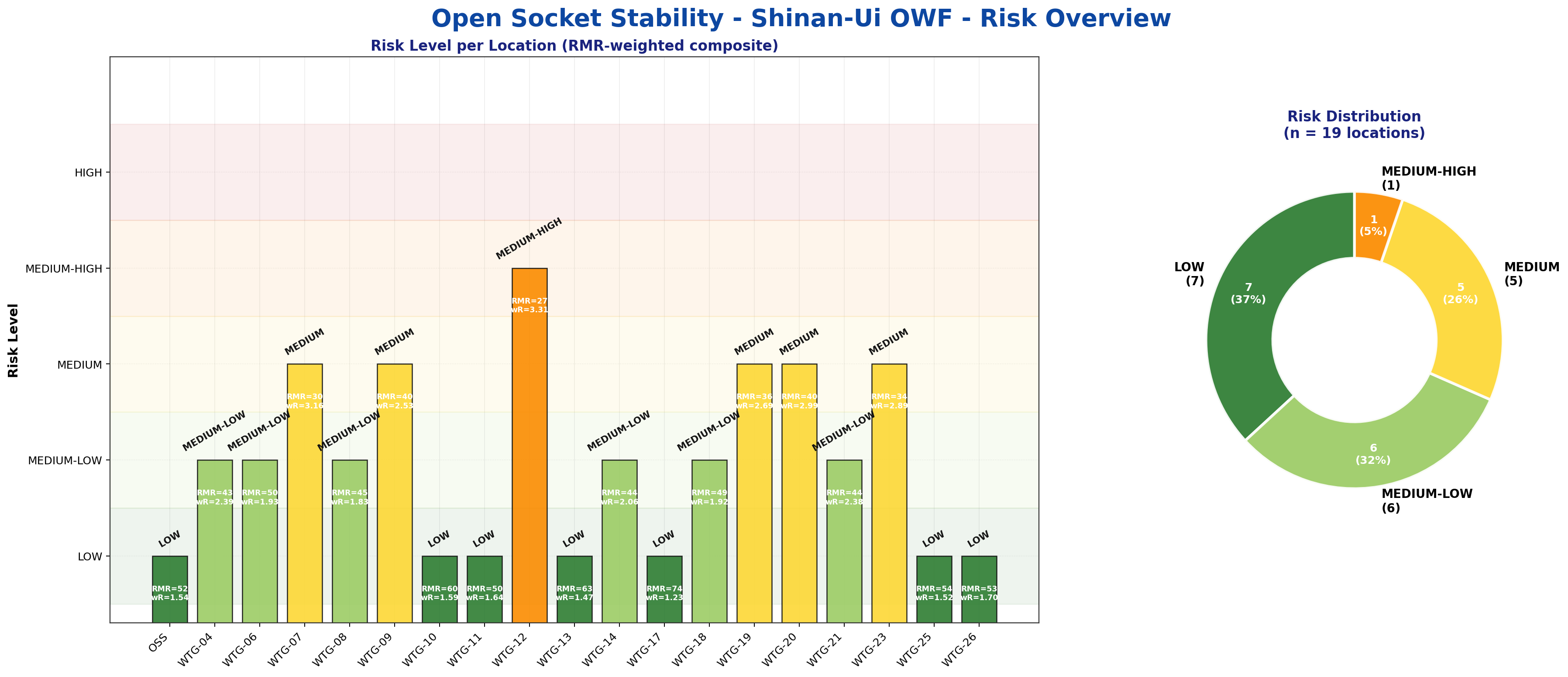
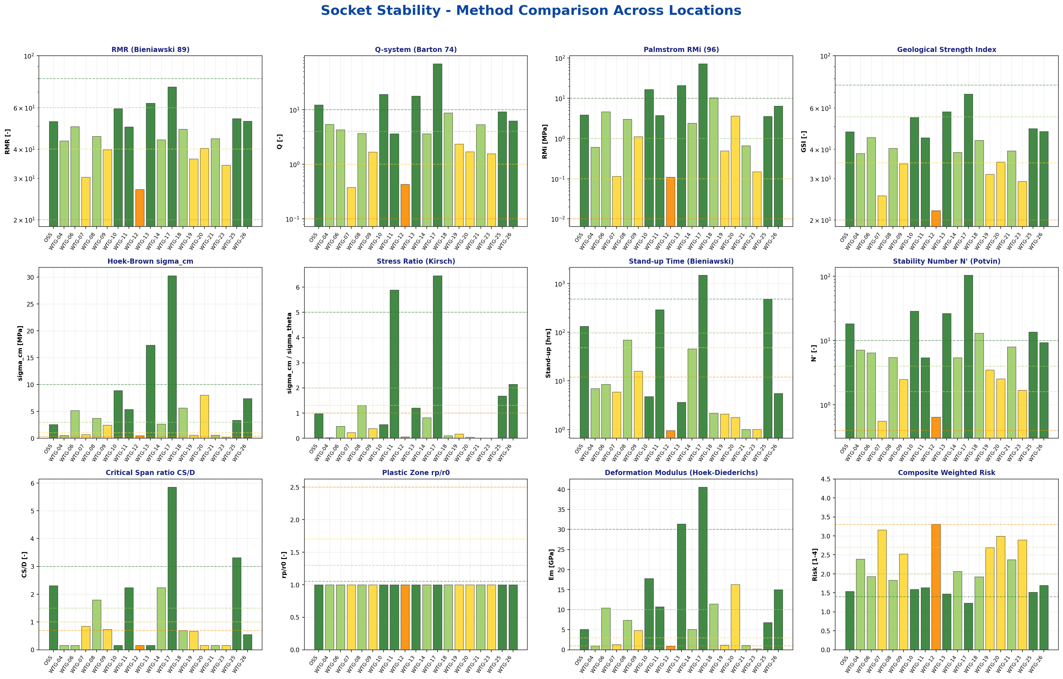
Drilled Rock Socket Stability
Shinan-Ui Offshore Wind Farm | Socket Ø3.2 m | 10 methods (RMR primary) | Required stand-up ≈ 24 h | Preliminary — for screening
19
Locations
6
LOW
5
MED-LOW
5
MEDIUM
1
MED-HIGH
0
HIGH
Methodology: Composite risk classification of the open rock socket (between driven pile tip and insert pile tip) using 10 independent rock-mechanics methods: RMR (Bieniawski 1989) & stand-up time (weight 3×), Q-system (Barton 1974), GSI / Hoek-Brown (2002), Kirsch stress ratio, Mathews-Potvin N' stability number, simplified SI, RMi (Palmström 1996), Critical Span (Hutchinson-Diederichs 1996), plastic zone radius (Panet 1995), Sakurai critical strain (1997). RMR adjustment −5 applied for vertical opening. Groundwater rating assumes managed drilling fluid. Scope: preliminary assessment to flag WTGs where casing, pre-mobilised grout, and tight stand-up-time control are recommended. Not a substitute for location-specific ground-control design.
📈
Risk Overview — All Locations
Composite risk bar chart and pie chart
📊
Method Comparison
How each of the 10 methods scores each location
📋
Per-Location Summary Table
Socket geometry, average rock properties, stand-up time, and overall risk
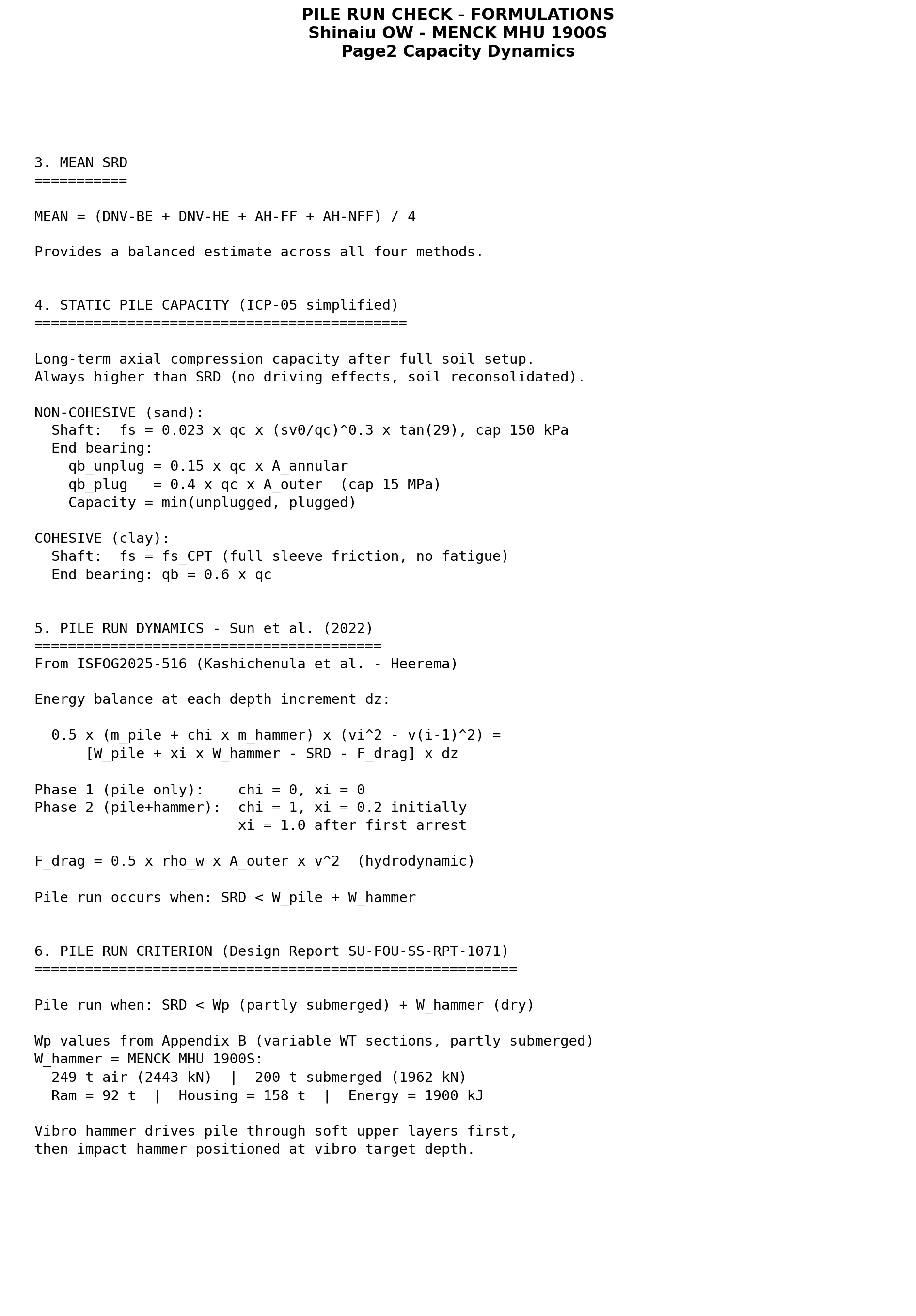
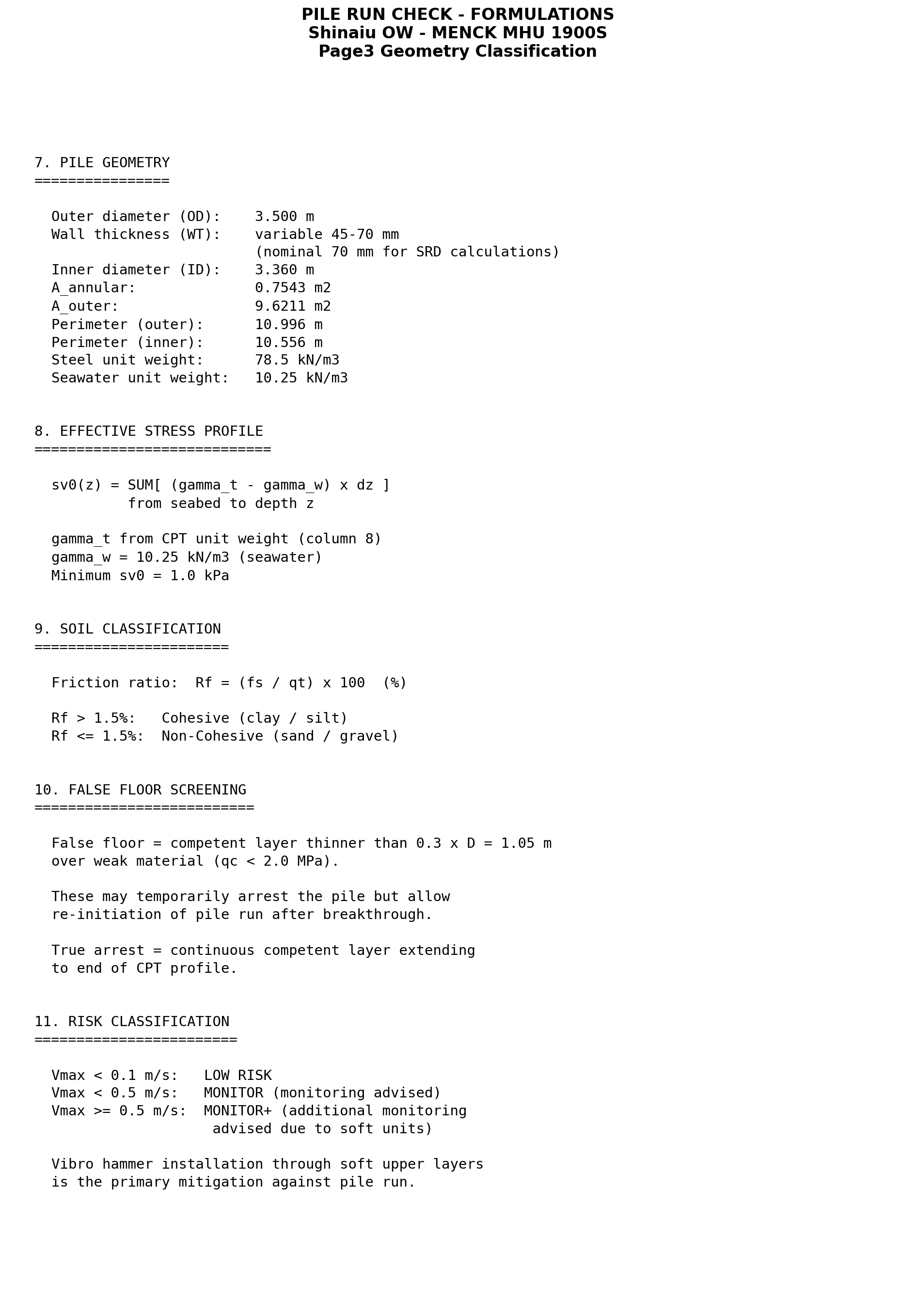
What is Pile Run? Pile run (or dropfall) occurs when the soil resistance to driving (SRD) is lower than the combined weight of the pile and impact hammer. The pile penetrates in an uncontrolled manner under gravity alone, which can lead to excessive penetration, damage, or unsafe conditions.
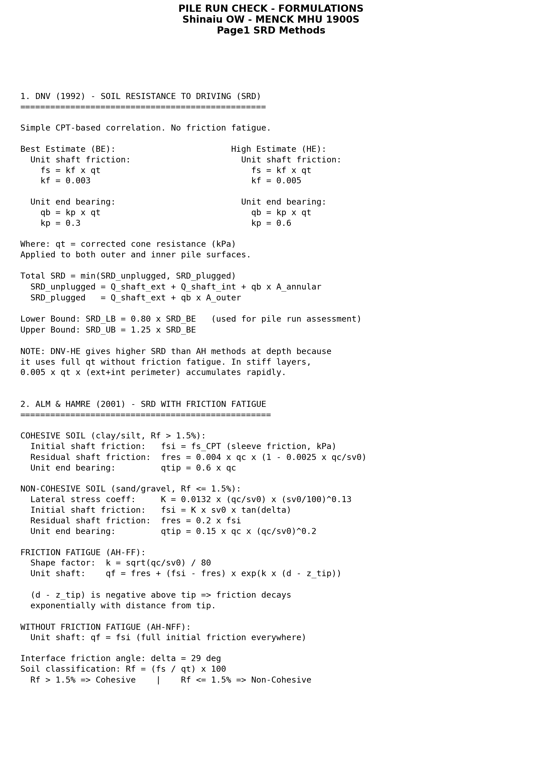
Methodology: Four SRD methods are applied at each location: Alm & Hamre (2001) with Friction Fatigue (AH-FF, lower bound), Alm & Hamre without Friction Fatigue (AH-NFF, upper bound), MEAN SRD (primary — average of AH-FF and AH-NFF), and Vergote et al. (2025) rate-dependent sensitivity check. Pile run dynamics are computed via the Sun et al. (2022) energy equation. The depth where velocity reaches zero defines the pile run arrest depth.
Risk Classification (MEAN SRD):OK = vibro depth >4 m below pile run end |
CAUTION = vibro depth 0–4 m below pile run end |
ATTENTION = pile run extends to/beyond vibro depth
Two-stage installation: Vibratory hammer (Cape Holland CV-320-5) drives pile through soft upper layers to a target depth where SRD exceeds combined pile + hammer weight; then the impact hammer (MENCK MHU 1900S) is placed for final driving. The safety margin is the gap between pile run arrest depth and the vibro target depth.
⚠ ATTENTION — WTG-19: Pile run end depth (MEAN SRD) reaches the vibro target depth (19.0 m). Safety margin = 0.0 m. Geotechnical engineer must be on site during hammer placement; apply hammer weight gradually with crane support. Verify CPT conditions match predictions before committing to changeover.
⚠ CAUTION locations (5): WTG-02 (margin 2.8 m), WTG-04 (3.5 m), WTG-15 (2.2 m), WTG-24 (0.5 m), WTG-26 (0.8 m). Close monitoring required — crane load readings during hammer placement, strict adherence to vibro target depth, and geotechnical engineer sign-off before releasing full hammer weight.
🏙
Wind Farm Layout — Pile Run Risk Classification
All 27 locations colour-coded by MEAN SRD pile run risk. Click any marker for details.
📍
Click a location on the map
Key pile run results will appear here
🌠
Risk Heatmap — All Locations
Pile run risk classification matrix across all 4 SRD methods
Filter:
📋
Per-Location Pile Run Results (MEAN SRD)
Pile weight, hammer weight (submerged), vibro target depth, pile run arrest depth, velocity, and safety margin
Last updated: 26 March 2026 · Status: Under Review · Subject to change
⚠ This section contains live updates. Information may change as new data and analysis results become available.
Key Ongoing Actions
1COWI re-run with 1900 kJ hammer: Client has requested COWI to rerun calculations using the 1900 kJ hammer, review results and potentially update fatigue and buckling checks for more robust and validated outcomes.
22H updated calculations: 2H will update their calculations using additional input data. However, with a 1900 kJ hammer driving in rock strata, the operation remains within a medium- to high-risk level scenario.
3Fatigue driving assessment divergence: Significant difference in fatigue assessment at WTG-22 between 2H and COWI identified — another key reason for the variation in results between the two.
4Proposed action: Gather updated COWI results for 1900 kJ hammer + 2H buckling/fatigue checks, then move towards a more conservative blow count refusal criterion to provide better control across all locations.
📊
Pile Installation & Drivability Data — All Locations
Pile geometry, rock head levels, blow count assessments (2H Offshore & COWI — Upper Bound), and refusal criteria
Location
PILE GEOMETRY
2H OFFSHORE
COWI
ASSESSMENT
Risk Score
Pile Tip (mbsb)
Rock Head (mbsb)
Pen. in Rock (m)
Driven into Rock
UB (bl/0.25m)
Result
UB (bl/0.25m)
Result
Refusal Criteria
Max Hammer Energy
!
2H Offshore Blow Count — Conservative Values Under Review
The following locations show significant divergence between 2H Offshore and COWI upper-bound blow counts. The 2H values appear too conservative and may contain errors. It is recommended to refer to the COWI method for these locations until the 2H results are reviewed and clarified.
Location
2H UB (bl/0.25m)
COWI UB (bl/0.25m)
Ratio (2H / COWI)
WTG-12
125
25
5.0x
WTG-16
125
27.5
4.5x
WTG-19
170
27.5
6.2x
WTG-21
150
16.2
9.3x
WTG-22
2,500
35
71.4x
Shinan-Ui OW · PIF Settlement Risk Map
Total pile settlement at all locations. Toggle between 1-day, 3-day, and 7-day consolidation. UB values shown. Locations with potential sinkage risk are flagged.
Settlement UB
≤ 40 mm
41–75 mm
76–110 mm
> 110 mm
Sinkage Risk
Settlement
0 mm
90+ mm
📈
Select a Location
Click on any WTG or OSS marker to view settlement data at 1, 3, and 7 days.
📊
PIF Settlement Data — All Locations
Total settlement (LB / UB) at 1 day, 3 days, and 7 days for all WTG locations and OSS
Location
1 DAY
3 DAYS
7 DAYS
Increase 1d→7d (UB)
Sinkage Risk
LB (mm)
UB (mm)
LB (mm)
UB (mm)
LB (mm)
UB (mm)
Shinan-Ui OW · Early Refusal Mitigation Measures
Pin Pile Refusal Contingency Scenarios and Decision Taking Process — Guidelines for offshore decision taking shall the Pin Pile refusal occur.
This Memo outlines initial guidelines regarding the Pin Pile refusal scenario during the Shinan-Ui Pin Piles installation campaign, describing checks required during preparation and at the moment of the occurrence of the refusal event during offshore execution.
It provides an initial basis for offshore decision taking process shall the Pin Pile refusal occur and an overall sequence of events to be used as reference by the HESI T&I and Construction teams for preparation of further and more detailed Contingency procedures.
Refusal Definition
During Vibrodriving: penetration rate (advancement / unit time) is below the refusal criteria
During Impact driving: number of blows per unit penetration exceeds the refusal criteria
2
Configuration of the Ongoing Installation Operation
The following conditions are assumed to be in place at the time of the refusal event:
1Pile Installation Frame (PIF) has been deployed to the seabed and levelled
2PIF survey activities performed — all parameters within required tolerances
3Installation Vessel (floating crane HLV) positioned at location via 8-anchor point arrangement
4Transportation Vessel with 4x Pin Piles moored alongside HLV
5Pin Pile upended via Vibrohammer, positioned and stabbed into PIF sleeve
6Hammering commenced — Vibrohammer for initial penetration, then Impact Hammer to target
3
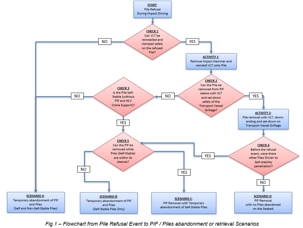
Decision Flowchart — From Refusal to Scenario
Starting from Pin Pile Refusal during Impact Driving, the following checks determine which post-refusal scenario (A, B, C or D) applies:
Fig 1 — Flowchart from Pile Refusal Event to PIF / Piles abandonment or retrieval Scenarios
CHECK 1 — Can Vibrohammer be reinstalled onto the refused pile?
Define elevation of Pin Pile top (in air / splash zone / underwater)
Define weather window requirements and check forecast
Check Vibrohammer guides/clamps suitability for pile top location
Check visibility and conditions for stabbing/clamping operations
YES → ACTIVITY 1NO → ACTIVITY 4 (go to Scenario A)
Mobilize JUV with drilling spread to refusal location
JUV drills to pre-defined depth, then alternate DDD with HLV impact driving
Drive refused piles to target penetration
Key Checks:
Verify HLV + JUV can operate at same WTG (positions, outreach, clashes)
Verify drill equipment suitability for rock layers and refusal mechanism
Evaluate if drilling underreaming is required (risk of pile run)
Check PIF re-installation feasibility (guiding bullets may be needed)
Note: According to risk/urgency, JUV work at other locations may be stopped to prioritise this contingency, achieving almost immediate availability.
2
Higher Capacity Impact Hammer
Mobilize larger hammer to drive refused pile to target
▼ Details
Evaluate whether higher energy hammer could drive refused pile to target
Inquiry supply chain for availability and lead time
Mobilize to HLV and perform impact driving
Note: Lead time may be excessive for high risk/urgency scenarios. Can be combined with other contingencies (e.g. higher capacity hammer for DDD).
3
Higher Capacity Vibrohammer — Pile Extraction
Extract refused pile to improve system stability
▼ Details
Evaluate if higher capacity vibrohammer can extract refused pile
Mobilize to HLV, perform extraction and recover pile to transport vessel
Note: This only improves stability — does not ensure full installation. Additional contingency needed afterwards.
4
Drive-Drill-Drive from JUV Only
Re-mob JUV with full drilling + PIF + impact hammer spread
▼ Details
Demob HLV and JUV, prepare JUV deck for PIF + impact hammer spread
Mobilize JUV with full installation and drilling spread
Re-install PIF, perform DDD from single vessel
Note: HLV not suitable for top drill (stability). Duration not compatible with high urgency. Expected after all base-case activities at all locations are completed.
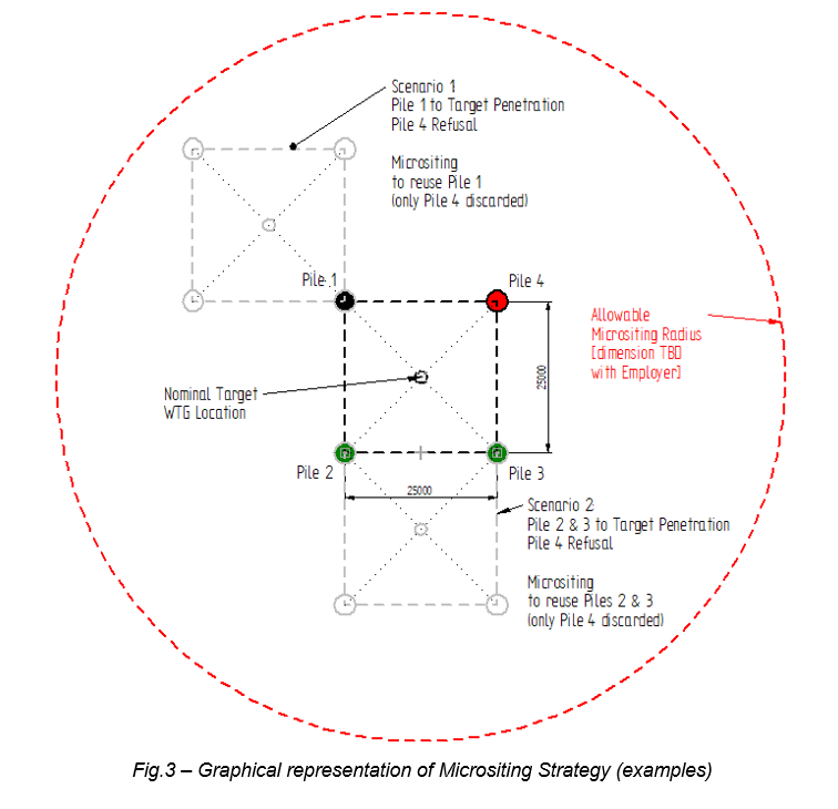
5
Micrositing Strategy
Relocate WTG foundation within allowable radius
▼ Details
Remove non-self-stable piles if needed
Define micrositing location (new PIF position)
Lift PIF and set-down at micrositing location
Continue pin pile installation as per base case
Key: Micrositing relocates within allowable radius — may reuse already-installed piles. Success depends on lateral soil variability.
Fig 3 — Graphical representation of Micrositing Strategy (examples)
6
Abandon Location — Install at Spare WTG
Abandon failed location and use pre-defined spare WTG position
▼ Details
Remove non-self-stable piles at original location
Define spare WTG location
Perform installation at spare location per base case
Requires: Spare WTG locations pre-defined by Employer/Designer. Updated drivability studies for new locations.
7
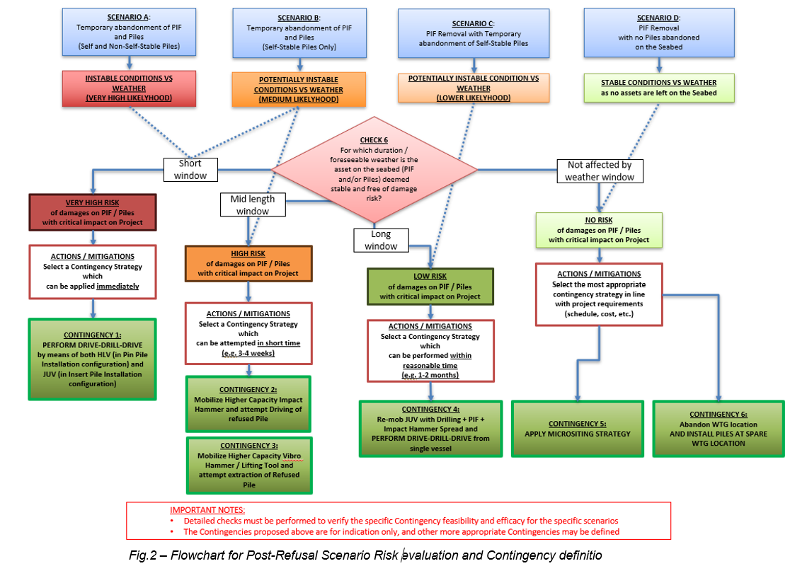
Contingency-Scenario Applicability Summary
Contingency
Scenario A
Scenario B
Scenario C
Scenario D
Urgency
1. Drive-Drill-Drive (HLV+JUV)
✓
✓
✓
✓
Immediate
2. Higher Capacity Hammer
✓
✓
✓
✓
Weeks
3. Higher Capacity Vibrohammer
✓
✓
—
—
Weeks
4. DDD from JUV Only
✓
✓
✓
✓
Months
5. Micrositing
—
✓
✓
✓
Weeks–Months
6. Abandon + Spare WTG
✓
✓
✓
✓
Months
Based on: HESI Memo — Pin Pile Refusal Contingency Scenarios and Decision Taking Process · Rev. A · 2026-03-25
PRELIMINARY — UNCHECKED · Content subject to further verification and update
Foundation & Installation Design Training Programme
Step-by-Step Plan of Action — From Fundamentals to Advanced Analysis
Leg penetration, spudcan stability envelope, fixity assessment. Spudcan-pile interaction. ISO/SNAME LPA, advanced methods. SSA input and management.
Week 1-2
Leg penetration assessment exercise. Spudcan stability envelope plot.
40%
7 hours of presentations introducing LPA topics, including punch-through risk, risk of spudcan penetration, and other key topics for LPA and LEA assessment. The aim is to explain scenarios for Anma OWF. Next step: complete internal tool for team calculations. Design inputs need to be developed from CPT data.
2
Regulatory Framework & Design Codes
Knowledge of standards/codes (API RP2A, EC7, ISO 19901-4, DNVGL ST-0126, DNV CN 30.4). Regulatory and legal requirements for offshore foundation design.
Week 3
Summary table of key codes per foundation type. Quiz on code applicability.
Soil thermal resistivity for cable rating calculations.
Not Started
0%
—
52
Pipeline & Cable
Upheaval Buckling Assessment
Uplift resistance and buckling check for buried pipeline.
Not Started
0%
—
53
Dynamic / EQ
1D Site Response Analysis (EERA)
Free-field ground response analysis using equivalent linear method.
Not Started
0%
—
54
Dynamic / EQ
Liquefaction Screening (CPT-Based)
Factor of safety against liquefaction using Robertson/Boulanger-Idriss.
Not Started
0%
—
55
Dynamic / EQ
Seismic Loading on Shallow Foundation
Bearing capacity and stability under seismic loading.
Not Started
0%
—
56
Dynamic / EQ
Seismic Loading on Pile Foundation
Pile response under earthquake loading, kinematic + inertial.
Not Started
0%
—
57
Numerical Modelling
PLAXIS 2D - Shallow FDN Bearing Capacity
FE verification of mudmat bearing capacity vs hand calc.
Not Started
0%
—
58
Numerical Modelling
PLAXIS 2D - Combined Loading (VHM) Swipe
Displacement-controlled analysis to derive failure envelope.
Not Started
0%
—
Documentation & Reference Library
Presentations, technical papers, design codes, calculation examples and training material for offshore foundation & T&I engineering
⌛Loading documents from library...
🏠 Home›LPA – Spudcan Penetration Assessment
Ready
⚠ Calculations currently for training purposes only — tool still in progress, not for project use ⚠
⚓
Spudcan Geometry
Define the equivalent three-section spudcan geometry and preload values
Basic Parameters
Spudcan maximum diameter (3 – 25 m)
Interface roughness (0 – 1)
Included angle at base tip (90 – 179°)
Depth of conical tip (0.01 – 3 m)
Shape – Height of Each Section
Section
Description
Height [m]
Volume [m³]
Top cone
Inverted cone at top
–
Mid cylinder
Cylindrical mid section
–
Base cone
Lower conical section
–
Total Vspudcan
–
–
Vbase (no backflow)
–
–
Preload Values
Primary preload (0 – 300 MN)
Secondary preload (0 = disabled, max 300 MN)
👁 Live Geometry Preview
–
Area A [m²]
–
Vspudcan [m³]
–
Total height [m]
–
Vbase [m³]
–
Base angle [°]
–
Roughness α
⚠ Calculations currently for training purposes only — tool still in progress, not for project use ⚠
🌎
Soil Profile
Define up to 8 soil layers. Layers are ordered top to bottom automatically.
Lower Bound (LB)
#
Soil Type
Top [m]
Bottom [m]
γ' [kN/m³]
su Top [kPa]
su Bot [kPa]
φ [°]
Interface below ↓
0 / 8 layers
Best Estimate (BE)
#
Soil Type
Top [m]
Bottom [m]
γ' [kN/m³]
su Top [kPa]
su Bot [kPa]
φ [°]
Interface below ↓
0 / 8 layers
⚠ Calculations currently for training purposes only — tool still in progress, not for project use ⚠
⚓
Analysis Settings
Configure calculation parameters, depth range and averaging methods
📊 Depth & Resolution
Deepest penetration depth (5 – 150 m)
Resolution of output depth profile
🌎 cu Averaging
Window below spudcan tip used to average undrained shear strength
📌 Punch-Through Method
Applies to Clay/Clay interfaces only. Sand/Clay (SNAME §C6.6) and Clay/Sand (SNAME §C6.5) interfaces have a single fixed formula — no alternative method exists in the standard. Single-layer profiles (uniform clay or uniform sand) always use SNAME.
▶ Backflow Conditions
Both curves always computed:No Backflow: displaced volume = Vbase (base cone only) Full Backflow: displaced volume = Vspudcan (entire spudcan)
⚠ Calculations currently for training purposes only — tool still in progress, not for project use ⚠
⚠️
Risk Assessment
Qualitative risk ratings based on results and site conditions — included in PDF report
Risk Category
Rating
Comments
Data Adequacy / Uncertainty
Punch Through Risk
Rapid Leg Penetration / Squeezing Risk
Scour Awareness
Boulder / Obstruction Risk
Extraction Risk
📊
Penetration Resistance Results
No Backflow and Full Backflow curves vs. tip depth
Run analysis to see preload depth crossings
⚠ Calculations currently for training purposes only — tool still in progress, not for project use ⚠
⚙
Extraction Parameters
Configure LEA-specific parameters — Purwana et al. (2010) method
🔧 Spudcan Extraction Geometry
Distance from spudcan tip to max bearing area (0.1 – 5 m)
Thickness of spudcan at max diameter (0.1 – 5 m)
📈 Reconsolidation & Shape Factors
Merifield et al. (2003) shape factor (1.0 – 3.0)
Reconsolidation factor for top backfill (0.1 – 1.5)
Reconsolidation factor for base reverse bearing (0.1 – 1.5)
Jack-up rig maximum extraction (pull) capacity (MN)
▶ Jetting Assumption
Both curves always computed:No Jetting: Qextraction = Qtop + Qbase (full resistance) With Jetting: Qextraction = Qtop only (jetting eliminates base suction)
Ready
📋
Extraction Summary
Key extraction resistance values at predicted penetration depth
📊
Extraction Resistance Results
Purwana et al. (2010) — Extraction resistance vs. tip depth
Run LEA to see extraction resistance profile
⚠ Calculations currently for training purposes only — tool still in progress, not for project use ⚠
Contents
Overview – Leg Penetration Assessment
The Leg Penetration Assessment (LPA) evaluates the resistance of the seabed to penetration of a jack-up rig spudcan. The analysis predicts the penetration resistance Qv [MN] as a function of tip depth, which is then compared to the preload applied during installation to determine expected penetration depth and assess punch-through risk.
This tool implements the procedures described in the SNAME T&R 5-5A (2002) guidelines, using the Xie et al. (2010) bottom-up multilayer stacking algorithm for profiles with multiple soil layers.
Key risk: Punch-through occurs when the spudcan penetrates rapidly through a stronger upper layer into a weaker lower layer. This can cause sudden large settlements and loss of rig stability. The LPA identifies this risk and predicts the depth at which it may occur.
Spudcan Geometry – Equivalent Model
The spudcan is modelled as three sections (SNAME 2002 Fig. C6.1):
Where D is the maximum diameter and htop, hmid, hbase are the heights of each section.
The base cone angle (included angle at the tip) is computed from: angle = 2 × arctan(D / (2 × hbase)) converted to degrees.
Clay – Single Layer Bearing Capacity
For a spudcan penetrating a uniform clay layer, the ultimate vertical bearing capacity follows the Skempton (1951) formulation as adopted in SNAME (2002):
No Backflow (Eq. C6.1)
Qv,nb = (Nc · su · sc · dc + p0') · A
Full Backflow (Eq. C6.2)
Qv,fb = Nc · su · sc · dc · A
The factors are computed as:
Symbol
Name
Formula / Value
Nc
Bearing capacity factor
5.14 (Skempton, 1951)
Nq
Surcharge factor
1.0 (for clay)
sc
Shape factor
1 + Nq/Nc = 1.194
dc
Depth factor
1 + 0.4 × D/B for D/B ≤ 1 1 + 0.4 × arctan(D/B) for D/B > 1
su
Undrained shear strength
Averaged over B/2 window below tip
p0'
Effective overburden at tip
∑ γ'i × hi
A
Bearing area
π × D² / 4
Reference
Skempton, A.W. (1951). The Bearing Capacity of Clays. Proceedings, Building Research Congress, London, Vol. 1, pp. 180–189.
SNAME (2002). T&R 5-5A Bulletin, Guidelines for Site Specific Assessment of Mobile Jack-Up Units.
Sand – Single Layer Bearing Capacity
For sand layers, the bearing capacity uses the Vesic (1975) formulation:
Sand Bearing Capacity (SNAME Eq. C6.3)
Qv = (0.5 · γ' · B · Nγ · sγ · dγ + p0' · Nq · sq · dq) · A
Reference
Vesic, A.S. (1975). Bearing Capacity of Shallow Foundations. Chapter 3 in Foundation Engineering Handbook (Winterkorn & Fang, eds). Van Nostrand Reinhold, New York.
Multilayer Algorithm – Xie et al. (2010)
For profiles with multiple soil layers, the Xie et al. (2010) bottom-up stacking algorithm is used. At each tip depth D, the algorithm:
Step 1: Compute overburden p0' at the current tip depth by summing contributions from all layers above.
Step 2: Start with the bearing capacity of the bottom-most layer (treated as a single layer).
Step 3: Walk upward through layers. For each interface between upper layer i and lower layer i+1:
Decision Rule (Xie et al. 2010)
If Qcombined < Qupper → Punch-Through
Qcombined = punch-through formula
Else → Squeezing
Qcombined = squeezing formula
Step 4: After all interfaces are processed, add the displaced volume term to account for soil weight:
Displaced Volume Terms
No Backflow: Qv,nb = Qbearing + γ' · Vbase
Full Backflow: Qv,fb = Qbearing + γ' · Vspudcan
Reference
Xie, Y., Leung, C.F., & Chow, Y.K. (2010). An analytical solution to spudcan penetration in multi-layer soils. Geotechnique Letters 1, pp. 7–12.
Punch-Through Failure Modes
Clay over Clay (General Term – SNAME 2002)
General Term Method (SNAME 2002 Eq. C6.5)
Qpt = A · (3 · (H/B) · cu,t + qb + p0')
Where H is the distance from spudcan tip to the lower layer interface, cu,t is the average undrained shear strength of the upper layer between current depth and interface, and qb = Qlower/A is the unit bearing pressure of the lower layer.
Qpt = Qv,b − A · H · γ'sand + 2 · (H/B) · (H · γ'sand + 2 · p0') · Ks tan φ · A
Ks tan φ = 3 · cu,iface / (B · γ'sand)
Squeezing Failure Modes
Clay Squeezing (Meyerhof & Chaplin 1953)
Clay squeezing occurs when spudcan diameter is large relative to layer thickness, causing lateral extrusion of clay.
Clay Squeezing (M&C 1953 / Skempton 1951)
Qsq = A · (5 + B/(3T) + 1.2 · D/B) · cu + p0' · A
Governs when: B ≥ 3.45 · T · (1 + 1.1 · D/B)
Where T is the thickness of the clay layer below the spudcan and cu is the average undrained shear strength over window min(B/2, T).
Sand Squeezing (Meyerhof 1974)
Sand Squeezing (Meyerhof 1974 / M&H 1978)
Qsq = Qtop + (Qbottom − Qtop) · (1 − H/d)<²
d = failure depth from SNAME Fig. C6.4 (function of φ)
Backflow Conditions
Two bounding conditions are considered for the soil displaced by spudcan penetration:
No Backflow (conservative upper bound for Qv)
Soil displaced upward — only the base cone volume is considered.
ΔQ = γ' · Vbase cone
Full Backflow (conservative lower bound for Qv)
Soil flows back over the spudcan — entire spudcan volume is displaced.
ΔQ = γ' · Vspudcan
(effective overburden p0' is NOT added in full backflow formulation)
In practice, the No Backflow curve gives a higher resistance (more conservative for punch-through). The Full Backflow curve gives lower resistance and is used for spudcan extraction assessments.
Leg Extraction Assessment — Purwana et al. (2010)
The Leg Extraction Assessment (LEA) predicts the force required to extract a jack-up spudcan from the seabed after operations. The methodology follows Purwana et al. (2010), which decomposes the total extraction resistance into two components:
Total Extraction Resistance
Qextraction = Qtop + Qbase
Qtop — Backfill resistance above the spudcan (breakout factor):
Qtop – Backfill Resistance
Qtop = (π/4) · B² · Nc,top · c̄u · Fg,top
Where Nc,top is determined by the embedment ratio Dt/B:
Dt/B < 1.0: Nc,top = S · 2.56 · ln(2)
Dt/B ≥ 1.0: Nc,top = min[ S · 2.56 · ln(2 · Dt/B) + γ' · Dt/c̄u , 12.56 ]
Qbase — Reverse bearing capacity (suction) below the spudcan:
Sb = 0 for Db/B ≤ 0.35
Sb = 0.87 · (Db/B) − 0.305 for 0.35 < Db/B ≤ 1.5
Sb = 1.0 for Db/B > 1.5
Symbol
Name
Description
B
Spudcan diameter
Maximum diameter of the spudcan (m)
Db
Depth of max bearing area
tip depth − htip
Dt
Backfill depth
Db − tspud (depth of soil above spudcan top)
c̄u
Average undrained shear strength
Mean cu from mudline to Db
cu,b
cu at base
Undrained shear strength at depth Db
S
Shape factor
1.8 (Merifield et al. 2003)
Fg,top
Reconsolidation factor (top)
Typically 0.6 (reconsolidated backfill)
Fg,base
Reconsolidation factor (base)
Typically 1.0 (intact soil below)
htip
Tip to max bearing area
Distance from spudcan tip to max diameter level
tspud
Spudcan thickness
Thickness of the spudcan at max diameter
γ'
Submerged unit weight
Effective (buoyant) unit weight of soil (kN/m³)
Jetting effect: When water jetting is applied beneath the spudcan during extraction, the base suction (Qbase) is effectively eliminated. In this case, Qextraction = Qtop only. This can significantly reduce the required extraction force, particularly at deeper penetrations in soft clay.
Factor of Safety: FoS = Max Pull Capacity / Qextraction. A FoS ≥ 1.5 is generally considered acceptable. If FoS < 1.5, extraction aids (jetting, cyclic loading, waiting for consolidation dissipation) should be considered.
Reference
Purwana, O.A., Leung, C.F., Chow, Y.K. & Foo, K.S. (2010). An assessment of jackup spudcan extraction. Proc. 2nd Int. Symp. on Frontiers in Offshore Geotechnics (ISFOG), Perth, Australia, pp. 597–602.
Merifield, R.S., Lyamin, A.V. & Sloan, S.W. (2003). Three-dimensional lower-bound solutions for the stability of plate anchors in sand. Géotechnique, 53(4), 385–397.
References
SNAME (2002). T&R Bulletin 5-5A: Guidelines for Site Specific Assessment of Mobile Jack-Up Units. Society of Naval Architects and Marine Engineers, 2nd Ed.
Xie, Y., Leung, C.F., & Chow, Y.K. (2010). An analytical solution to spudcan penetration in multi-layer soils. Geotechnique Letters, 1, 7–12.
Vesic, A.S. (1975). Bearing Capacity of Shallow Foundations. In: Foundation Engineering Handbook (Winterkorn & Fang, eds.), Van Nostrand Reinhold.
Skempton, A.W. (1951). The Bearing Capacity of Clays. Proc. Building Research Congress, London, Vol. 1, 180–189.
Meyerhof, G.G. & Chaplin, T.K. (1953). The Compression and Bearing Capacity of Cohesive Soils. British Journal of Applied Physics, 4, 20–26.
Meyerhof, G.G. (1974). Ultimate Bearing Capacity of Footings on Sand Layer Overlying Clay. Canadian Geotechnical Journal, 11(2), 223–229.
Brown, J.D. & Meyerhof, G.G. (1969). Experimental Study of Bearing Capacity in Layered Clays. Proc. 7th Int. Conf. on Soil Mechanics, Mexico City, 2, 45–51.
Osborne, J.J. et al. (2011). The InSafeJIP — improved methodologies for jack-up site assessment. Frontiers in Offshore Geotechnics II, Taylor & Francis.
Purwana, O.A., Leung, C.F., Chow, Y.K. & Foo, K.S. (2010). An assessment of jackup spudcan extraction. Proc. 2nd Int. Symp. on Frontiers in Offshore Geotechnics (ISFOG), Perth, 597–602.
Merifield, R.S., Lyamin, A.V. & Sloan, S.W. (2003). Three-dimensional lower-bound solutions for the stability of plate anchors in sand. Géotechnique, 53(4), 385–397.
🏠 Home›4-Point Rigging Design Calculator
⚠ Calculations currently for training purposes only — tool still in progress, not for project use ⚠
🗒 4-Point Rigging Arrangement — Overview
📦 Module Properties
🎯 Centre of Gravity
Origin: grid under LP3 (bottom-left corner when looking from above)
⚠ Calculations currently for training purposes only — tool still in progress, not for project use ⚠
📊 Load Chain & Sling Geometry
⚓ Design Factors
📈 Skew Load Parameters
⚠ Calculations currently for training purposes only — tool still in progress, not for project use ⚠
📍 Lifting Point Coordinate Reference
LP1 — C3
LP2 — C4
LP3 — A3
LP4 — A4
⚠ Calculations currently for training purposes only — tool still in progress, not for project use ⚠
🔧 Working Dimension (WD) — Component Breakdown
LP1 — Sling & Shackle
LP2 — Sling & Shackle
LP3 — Sling & Shackle
LP4 — Sling & Shackle
⚠ Calculations currently for training purposes only — tool still in progress, not for project use ⚠
Click Run Calculation to compute rigging design results
⚠ Calculations currently for training purposes only — tool still in progress, not for project use ⚠
📐 Key Concepts — Visual Reference
📖 Theory & Methodology
1. Working Dimension (WD)
The working dimension is the effective length from hook centre to lifting point, accounting for bending losses at shackle eyes and hook contact. WD = Dpin/2 + Linside + Lsling + Linside + Dpin/2 + BL − Dhook/2, where BL is the sum of bending losses at each contact point.
2. Centre of Hook (CoH)
The CoH is determined by the intersection of four spheres centred at each lifting point with radii equal to their working dimensions. The 3D intersection is solved by reducing 4 sphere equations to 3 linear equations and solving via matrix methods.
3. Load Distribution
Vertical load distribution uses bilinear interpolation based on CoG position relative to the quadrilateral formed by the four lifting points. The fraction per LP depends on the ratios of distances from CoG to opposite LP pairs.
4. Sling Design Load (SDL)
SDL = FV / sin(α − αinaccuracy), where FV is the vertical load per LP and α is the sling angle from horizontal. The inaccuracy deduction (typically 2.5°) accounts for as-built geometry tolerances.
5. Safety Factors & Unity Checks
Per DNV-OS-H205 / IMCA M179:
Bending reduction factor (γb): 1/(1 − 0.5 × D/d) at hook and shackle eye bends
Termination factor (γs): 1.82 for hand-spliced cable laid slings
Per DNV-OS-H205 Appendix A: SKL = 1 + (ε0) / (ε + εadd), where ε0 is length tolerance strain, ε is average elastic strain from DHL, and εadd = 0.0035 × cos(θ).
7. Tilt Calculation
Module tilt results from the eccentricity between CoH projection and CoG. Tilt% = e/(ZCoH − ZCoG) × 100, where e = √(eX² + eY²). Absolute tilt per LP is derived from the X and Y tilt components.
References
DNV-OS-H205 (April 2014) — Lifting Operations (VMO Standard Part 2-5)
IMCA M179 — Guidance on use of Cable Laid Slings and Grommets
DNV-ST-N001 — Marine Operations and Marine Warranty
🏠 Home›SRD – Pile Drivability Assessment
Ready
⚠ Calculations currently for training purposes only — tool still in progress, not for project use ⚠
🔩
Monopile Geometry
Define the pile external diameter, wall thickness and tip depth
Pile Parameters
Pile outer diameter (0.5 – 15 m)
Steel wall thickness (0.01 – 0.2 m)
Maximum penetration depth below mudline
Derived Values
⚠ Calculations currently for training purposes only — tool still in progress, not for project use ⚠
📈
CPT Data Input
Paste or enter CPT data. Columns: Depth [m], Total Stress [kPa], Effective Stress [kPa], qc [MPa], fs [MPa], Interface Friction Angle [°], Friction Angle [°], UCS [MPa]
📖 How to prepare your CPT data
Source: Pre-processed CPT data from AGS files or interpreted geotechnical spreadsheets. The data should already include computed stress values and interpreted strength parameters.
Format: Copy & paste from Excel, or use tab-separated or comma-separated text. The first row must be a header row (any header names are fine — columns are read by position, not name).
Required columns (in this exact order, left to right):
Col #
Parameter
Unit
AGS Field
Description
1
Depth
m
SCPT_DPTH
Depth below mudline
2
Total Vertical Stress (σv)
kPa
SCPT_CPO
Total overburden stress at depth
3
Effective Vertical Stress (σ'v)
kPa
SCPT_CPOD
Effective overburden stress at depth
4
Cone Resistance (qc)
MPa
SCPT_QT
Corrected cone resistance (qt for piezocone)
5
Sleeve Friction (fs)
MPa
SCPT_FRES
Local unit side friction resistance
6
Interface Friction Angle (δ)
°
INTERFACE_friction_angle_deg
Pile-soil interface friction angle (for sand/rock). Set 0 for clay.
7
Friction Angle (φ)
°
Friction_angle_deg
Soil internal friction angle (for sand). Set 0 for clay.
8
UCS
MPa
UCS
Unconfined Compressive Strength (for rock layers only). Set 0 if no rock.
Important notes:
Units matter: qc and fs must be in MPa (as typical in AGS format). Stresses must be in kPa. The tool converts internally to kPa for calculations.
Non-cohesive layers: δ and φ should have values > 0. For cohesive (clay) rows, set them to 0.
Rock layers: UCS column is only needed if you have rock. For non-rock rows, set UCS to 0.
Missing data: If a column is missing or blank, it defaults to 0. Columns 6–8 are optional if you have no sand or rock.
Data spacing: Typical CPT interval is 0.02–0.05 m. You can use filtered/reduced data (e.g. every 0.5 m) for faster computation.
Copy from Excel: Select your range in Excel, Ctrl+C, then Ctrl+V into the text box below. Excel copies as tab-separated by default, which works perfectly.
Paste your tab-separated or comma-separated CPT data below (first row = headers):
Excel/CSV upload: Reads the first sheet of your file. First row = headers (skipped). Columns by position: 1=Depth [m], 2=σv [kPa], 3=σ'v [kPa], 4=qc [MPa], 5=fs [MPa], 6=δ [°], 7=φ [°], 8=UCS [MPa]. Columns 6–8 are optional (default to 0).
Row
Depth [m]
σv [kPa]
σ'v [kPa]
qc [MPa]
fs [MPa]
δ [°]
φ [°]
UCS [MPa]
⚠ Calculations currently for training purposes only — tool still in progress, not for project use ⚠
🌏
Soil Layer Assignment
Define depth ranges and assign soil types (Cohesive, Non-Cohesive, Glauconite, Rock). Each CPT row will be assigned the soil type of the layer it falls within.
#
Soil Type
From Depth [m]
To Depth [m]
Stratigraphy & Pile
⚠ Calculations currently for training purposes only — tool still in progress, not for project use ⚠
⚙
Analysis Settings
Configure method parameters and adjustment factors
Cohesive Soil (Alm & Hamre)
These factors adjust the Alm & Hamre (2001) cohesive method. They act as direct multipliers on the computed values:
• Factor qp scales the unit end bearing: qb = 0.6 · qc · Factor. Increase >1 if back-analysis shows higher tip resistance; decrease <1 for conservative estimates.
• Factor VW scales the unit shaft friction after friction fatigue. Useful for calibrating against back-analysed driving records or OPILE results. If your clay is a silty/hard mixture, you may need to adjust this.
Leaving both at 1.0 gives the standard Alm & Hamre formulation.
Multiplier on qb = 0.6·qc. Default = 1.0
Multiplier on cohesive qf after fatigue. Default = 1.0
Non-Cohesive Soil (Alm & Hamre)
The lateral stress coefficient K controls the initial shaft friction in sand: qf,i = K · σ'v · tan(δ).
K is computed as: K = 0.0132 · (qc/σ'v) · (σ'v/100)0.13.
• K factor is a global multiplier applied to K. Increase >1 to raise sand shaft friction (e.g. dense sand with high lateral stress). Decrease <1 for loose sand or conservative estimates.
• Non-cohesive shaft friction is applied to the external surface only (not internal), following COWI practice.
Leaving at 1.0 gives the standard formulation.
Multiplier on qb = 0.15·qc·(qc/σ'v)0.2. Default = 1.0
Global multiplier on K. Default = 1.0
Depth-Dependent K Adjustment (optional — leave at 1.0 for uniform K):
Shallow zone
Mid zone
Transition zone
Deep zone
Glauconite (NGI Modified – RAM Approach)
For glauconite-rich soils, the NGI modified method uses CPT sleeve friction with calibration coefficients:
qf = a · fs · max(1, z/D)c · (1 − (Dint/Dext)²)b
• a – Primary scaling factor on sleeve friction. Higher a = more shaft friction. Typically 0.5–1.2.
• b – Exponent on the pile geometry term. Controls how much the Dint/Dext ratio reduces friction. Typically 0.05–0.2.
• c – Depth normalisation exponent. If c=0, no depth effect. If c>0, deeper layers get more friction (depth/diameter scaling).
Glauconite shaft friction has no friction fatigue (no exponential decay with pile advance). End bearing = 0.25·qc.
Scaling factor on fs. Default = 0.8
Geometry exponent. Default = 0.1
Depth exponent. 0 = no depth effect. Default = 0
Rock Parameters
Rock end bearing uses Stevens (1982): qb = UCS · Nc,r. Three methods are available for rock shaft friction:
1. COWI Clay-like – Treats weathered rock like cohesive soil. Uses fsi = fs,CPT with the same friction fatigue exponential decay as clay. Shaft friction is applied on both internal and external pile surfaces. Best for highly weathered, clay-like rock.
2. COWI Sand-like – Treats rock like coarse-grained soil. Uses K-based effective stress method with friction fatigue. Shaft friction applied on external surface only. Best for competent, granular-weathered rock.
3. Kadivar UCS-based – Uses empirical UCS correlations (Kadivar et al.) without friction fatigue. The weathering profile controls which equation is used. Best when UCS data is reliable and you want a direct strength-based estimate.
• Nc,r – Increase for stronger/more competent rock (typ. 3–5). Decrease for fractured/weak rock.
• Max qf Rock – Upper cap on rock shaft friction to prevent unrealistically high values. Typically 1000–5000 kPa depending on rock quality.
Higher = more tip resistance. Default = 3.5
Controls how rock shaft friction is calculated
Only used when Kadivar method is selected
Cap on rock shaft friction. Default = 5000 kPa
Internal Friction
During driving, soil enters the open-ended pile and creates internal shaft friction. This factor reduces the internal friction contribution:
Qf,int = π · Dint · qf · NGI Factor · Δz
• 1.0 = full internal friction (default, conservative – higher SRD).
• < 1.0 = reduced internal friction. Use if you expect the soil plug to slide inside the pile with less resistance (e.g. very soft clay, or partial plugging assumed). Typical range 0.5–1.0.
• 0 = no internal friction at all (fully coring, no plug resistance).
Note: Internal friction only applies to cohesive, glauconite, and rock (clay-like) layers. Non-cohesive (sand) is always external only.
1.0 = full internal friction, 0 = no internal friction
GRLWEAP Parameters
These parameters are included in the GRLWEAP input table export. They do not affect the SRD calculation itself — they are passed through to the wave equation analysis software.
• Quake – Maximum elastic deformation of the soil [mm]. Skin quake = shaft, toe quake = base. Typical values: 2.5 mm for both. Higher quake = softer soil response in GRLWEAP.
• Damping – Viscous damping resistance [s/m]. Typical: skin = 0.15–0.65 s/m (clay higher, sand lower), toe = 0.5 s/m. Higher damping = more velocity-dependent resistance in GRLWEAP.
These values appear in the CSV export and can be adjusted before importing into GRLWEAP.
Each line represents a different pile tip position. As the pile advances deeper, soil above the tip loses shaft friction due to friction fatigue (exponential decay). These plots visualise how the resistance envelope changes with penetration.
Depth [m]
Unit Shaft Fric. [kPa]
Unit Toe Res. [kPa]
SRD [kN]
SRD [MN]
Qf Ext [kN]
Qf Int [kN]
Qp Coring [kN]
Summary
Max SRD
-
Depth at Max SRD
-
SRD at Pile Tip Depth
-
Max Shaft Resistance
-
Max Tip Resistance
-
⚠ Smith (1960) 1D wave equation model — for training and preliminary estimates. Always verify with certified GRLWEAP analysis for final design. ⚠
🔨
Blow Count Analysis – Smith (1960) Wave Equation
Full 1D wave equation analysis with discretized pile, stress wave propagation, and elastic-plastic soil springs with Smith damping. Requires SRD results from Step 5.
🔨 Smith (1960) 1D Wave Equation — This tool implements the full discretized Smith model:
• Pile discretized into 1m lumped-mass segments connected by springs (EA/L)
• Stress wave propagation solved with explicit time integration (dt ≈ 0.1 ms, CFL-stable)
• Ram, helmet/cap, and cushion modelled as separate masses with spring connections
• Elastic-plastic soil springs at each segment with Smith viscous damping (R = R_s + J·R_s·v)
• Ram separation modelled (no tension in cushion spring)
• Permanent set = max toe displacement − weighted average quake (GRLWEAP Eq. 3.39–3.41)
Note: No residual stress analysis (RSA), no soil setup/relaxation, no multi-blow convergence. For certified design, verify with GRLWEAP.
Hammer Properties
Select a hammer type and enter its properties. The rated energy and ram weight are the key parameters. Typical offshore hydraulic impact hammers: 1500–5000 kJ, ram weight 500–3000 kN, stroke ~2.0 m.
Type of driving hammer
Max energy per blow. Typ. 1500–5000 kJ for offshore monopiles
Weight of falling ram. Typ. 500–3000 kN for offshore hammers
GRLWEAP: Hydraulic ~95%, Diesel ~80%, Drop ~60%
Ram Stroke (Fall Height): The stroke is the distance the ram falls before impact. For offshore hydraulic hammers, Erated ≈ Wram × hstroke (e.g. 1000 kN × 2.0 m = 2000 kJ).
Reducing the stroke is the primary way operators control energy during installation (e.g. soft-start at 0.5–1.0 m stroke, full energy at ~2.0 m stroke). In "Stroke" mode, blow counts will change as you vary the stroke height.
"Rated Energy" = use kJ value above. "Stroke" = E from fall height.
Typ. 1.8–2.1 m for offshore hydraulic. Soft-start: 0.5–1.0 m.
-
Gravity-only energy from ram weight × stroke height
• Coefficient of restitution (e) – Ratio of rebound to impact velocity at the ram-pile interface. Steel-on-steel ~0.5, with cushion ~0.3–0.4.
• Helmet + cushion weight – Added mass between ram and pile head. Reduces energy transfer.
• Energy reduction – Fraction of hammer energy actually reaching the pile (accounts for cushion/cap losses). Typically 0.7–0.95.
0.5 = steel/steel, 0.3 = with cushion
Added mass at pile head. 0 if none.
Cushion/cap energy loss. 0.85 typical.
Pile Properties
Length of pile above seabed (adds to pile mass)
Self-Weight Penetration
Before hammering begins, the pile penetrates under its own weight (plus any crane vertical load, follower weight, or hammer weight sitting on top). The tool compares this total driving weight against the SRD at each depth — wherever SRD < driving weight, the pile penetrates freely (0 blows). Hammering only starts when SRD exceeds the driving weight.
• Driving weight = pile self-weight + hammer weight + additional vertical load (crane push, follower, etc.)
• The pile self-weight increases with depth as more steel enters the ground.
Crane push, follower weight, etc. Set 0 if none.
Whether hammer weight pushes pile down
Refusal Criteria
Refusal is defined as the blow count exceeding a threshold. Per GRLWEAP practice:
• Practical refusal: >800 blows/m (240 bl/ft, 20 bl/in) — driving becomes inefficient
• Hard refusal: >1200 blows/m (360 bl/ft, 30 bl/in) — driving must stop
• Fatigue limit: Total blow count limited to control pile fatigue (typical 5000–15000 blows)
Blow count above this = practical refusal
Fatigue blow count limit for entire drive
Ready
Analysis Summary
Pile Impedance Z
-
Ram Stroke
-
Energy at Impact
-
Impact Velocity
-
Peak Driving Stress
-
Wave Speed c
-
Drivability Summary
Self-Weight Pen.
-
Hammering Starts At
-
Max Blow Count
-
Depth at Max BC
-
Blow Count at Tip
-
Total Blows
-
Refusal Depth
-
Drivability
-
Blow Count Table
Depth [m]
SRD [kN]
Set/Blow [mm]
Blows/m
Cum. Blows
Driving Stress [MPa]
Status
📚
Theory & References
Alm & Hamre (2001) SRD methodology
1. Cohesive Soil – Alm & Hamre (2001)
Unit Shaft Friction:
qf,i = fs (initial, from CPT sleeve friction)
qf,res = 0.004 · qc · (1 − 0.0025 · qc / σ'v0)
k = (qc / σ'v0)0.5 / 80
qf = qf,res + (qf,i − qf,res) · exp(k · (d − p))
Unit End Bearing: qb = 0.6 · qc
2. Non-Cohesive Soil – Alm & Hamre (2001)
Unit Shaft Friction:
K = 0.0132 · (qc/σ'v0) · (σ'v0/100)0.13
qf,i = K · σ'v0 · tan(δ)
qf,res = 0.2 · qf,i
qf = qf,res + (qf,i − qf,res) · exp(k · (d − p))
Unit End Bearing: qb = 0.15 · qc · (qc/σ'v0)0.2
3. Glauconite – NGI Modified (RAM)
Unit Shaft Friction: qf = a · fs · max(1, z/Dext)c · (1 − (Dint/Dext)²)b
Unit End Bearing: qb = 0.25 · qc
4. Rock
End Bearing (Stevens 1982): qb = UCS · Nc,r
Shaft Friction – COWI Clay-like: Same as cohesive (fsi = fs,CPT) with friction fatigue, applied to both internal and external surfaces.
Shaft Friction – COWI Sand-like: Same as non-cohesive (K-based) with friction fatigue, applied to external surface only.
Highly to Moderately: fs = 0.696·UCS / (0.75+2.088·UCS)0.75
Highly weathered: fs = 0.127·UCS0.54
5. Friction Fatigue
As the pile penetrates deeper, soil above the tip experiences friction fatigue. The exponential decay factor exp(k · (d − p)) reduces the shaft friction from its initial value towards the residual value. At the pile tip (d=p), there is no reduction. Further above the tip, the reduction increases exponentially.
6. Total SRD
SRD = Qf,external + Qf,internal + Qp,coring
Qf,ext = Σ(π · Dext · qf · Δz) for all soil types
Qf,int = Σ(π · Dint · qf · Δz) for cohesive + glauconite (+ rock if clay-like)
Qp,coring = π/4 · (Dext² − Dint²) · qp
7. Blow Count Analysis – Smith (1960) 1D Wave Equation
This tool implements the Smith (1960) one-dimensional wave equation — the same fundamental method used by GRLWEAP. The pile is discretized into lumped-mass segments connected by springs, and the stress wave propagation from each hammer blow is simulated in the time domain using explicit finite-difference integration.
Unlike simplified energy-balance formulas (Hiley, Gates, ENR), the Smith model correctly captures wave propagation effects: the stress wave travels at ~5100 m/s through the steel pile, reflects off soil resistance and the pile toe, and the pile segments move independently rather than as a rigid body. This is critical for long offshore piles where the pile length greatly exceeds the stress wave pulse length.
7.1 Input Parameters — What Each Input Does
Understanding each input parameter is essential for producing realistic blow count predictions. Below is a detailed explanation of every input, what it physically represents, and how it feeds into the calculation.
Hammer Properties
Parameter
What it is
How it feeds into the calculation
Typical range
Rated Energy [kJ]
Maximum energy the hammer can deliver per blow at full stroke, as stated by the manufacturer
Multiplied by efficiency to give kinetic energy of ram at impact: Eimpact = Erated × η. This sets the initial velocity of the ram in the Smith model.
1500–5000 kJ
Ram Weight [kN]
Weight of the falling ram (the heavy mass that strikes the pile head). This is the main moving part of the hammer.
Converted to mass Mram = W / g, then used to compute impact velocity: v = √(2E / M). Heavier ram at same energy = lower velocity but more momentum = better energy transfer to heavy piles.
500–3000 kN
Ram Stroke h [m]
The fall height of the ram before impact. This is the distance the ram travels (under gravity + hydraulic push) before hitting the pile head.
In "Stroke" mode: E = Wram × h (gravity energy). In "Rated Energy" mode: stroke is shown for reference only. Reducing the stroke is how operators reduce energy during soft-start or when approaching refusal.
0.5–2.1 m
Efficiency η [%]
Fraction of rated energy that becomes kinetic energy of the ram at the moment of impact. Losses come from friction in guides, misalignment, and pre-compression of air.
Eimpact = Erated × η. Directly scales the ram velocity and therefore the force of impact. Higher efficiency = harder blow.
Hydraulic: 95% Diesel: 80% Drop: 60%
Energy Transfer & Dynamics
Parameter
What it is
How it feeds into the calculation
Typical range
Coeff. of Restitution e
Ratio of rebound velocity to impact velocity at the ram-pile interface. Measures how "bouncy" the impact is. Steel-on-steel is more elastic (higher e); with a cushion, more energy is absorbed (lower e).
Used in the Smith model for ram rebound after impact. Higher e = more energy returns to the ram (wasted), less goes into the pile. In the Smith solver, the cushion spring handles this naturally.
0.3–0.5
Helmet + Cushion Weight [kN]
The driving helmet (cap) sits on top of the pile and absorbs/distributes the blow. The cushion is a pad between the ram and the helmet. Together they add mass between the ram and the pile.
Modelled as a separate lumped mass in the Smith model, connected to the ram via the cushion spring and to the pile top via a stiff spring. Heavier helmet = more momentum but slower response.
10–100 kN
Energy Reduction Factor
Fraction of hammer energy that actually reaches the pile after losses through the cushion, cap, and helmet. Accounts for hysteretic (heat) losses in the cushion material.
Used to compute the delivered energy shown in the summary (Edelivered = Erated × η × reduction). Also controls the cushion spring stiffness in the Smith model: stiffer cushion = higher reduction factor = more energy transfer.
0.75–0.95
Soil Model Parameters (Quake & Damping)
Parameter
What it is
How it feeds into the calculation
Typical range
Shaft Quake Qs [mm]
Maximum elastic deformation of the soil along the pile shaft before it yields (goes plastic). Think of it as the "spring travel" of the soil spring.
Soil spring is linear up to Q, then perfectly plastic beyond Q. Higher quake = more energy absorbed elastically = less permanent set = higher blow count. This is "wasted" energy that doesn't advance the pile.
2.5 mm (standard)
Toe Quake Qt [mm]
Same as shaft quake but for the pile toe (tip). Can be larger for soft soils or smaller for rock.
Same mechanism as shaft quake. For open-ended piles on rock, use 1.0 mm. For soft soil, up to D/60.
1.0–2.5 mm
Shaft Damping Js [s/m]
Smith viscous damping coefficient for shaft resistance. Represents the velocity-dependent component of soil resistance — faster pile motion = more resistance.
Rdynamic = J × Rstatic × v. Higher J = more energy lost to viscous damping = higher blow count. Clay has much higher damping than sand (clay is more viscous).
Sand: 0.16 Clay: 0.65 Silt: 0.33
Toe Damping Jt [s/m]
Same as shaft damping but for the pile toe. Typically 0.50 for all soil types (GRLWEAP recommendation).
Same formula: Rd,toe = Jt × Rs,toe × vtoe. Since the toe moves faster than shaft segments, toe damping has a significant effect.
0.50 (all soils)
Refusal & Drivability Criteria
Parameter
What it is
How it feeds into the calculation
Typical range
Refusal Limit [bl/m]
The blow count threshold above which driving is considered impractical or risks equipment damage. If the predicted blow count exceeds this, the pile is flagged as "refusal".
Used to flag rows in the results table and to determine the refusal depth (deepest penetration before blow count exceeds limit). Also used for the drivability verdict.
800–1200 bl/m
Max Total Blows
Upper limit on the cumulative number of hammer blows over the entire driving sequence. Exceeding this risks fatigue damage to the pile steel.
Compared against the cumulative blow count. If exceeded, the drivability verdict flags "fatigue risk". Typical limit is 5,000–15,000 blows.
5000–15000
Understanding the Two Energy Input Modes
"Use Rated Energy" (default)
You enter the manufacturer's rated energy directly in kJ. The tool computes the equivalent stroke as h = Erated / Wram for display. Use this when you know the hammer specs from the data sheet.
You set the stroke height in metres, and the energy is calculated as E = Wram × h. Use this to model reduced-energy driving (soft-start, approaching refusal, or when the vessel master requests lower energy).
Example: 1000 kN ram at 1.0 m stroke → E = 1000 kJ (half energy)
7.2 The Smith Model
The hammer-pile-soil system is idealized as a chain of lumped masses connected by springs:
System discretization:
• Ram — single mass Mram with initial velocity v0 = √(2·Edelivered/Mram)
• Helmet/cap — single mass Mhelmet, connected to ram via cushion spring
• Pile — N segments (typically 1m each), each with mass mi = ρ·A·ΔL and connected by springs k = E·A/ΔL
• Soil — at each embedded pile segment: elastic-plastic spring (quake Q, ultimate resistance Ru) + viscous dashpot (Smith damping J)
The simulation runs in time steps of ~0.1 ms. At each step: spring forces are computed between adjacent masses, soil resistance is evaluated, and velocities/displacements are updated. The permanent set emerges naturally from the simulation — no energy balance formula is needed.
7.3 Equation of Motion (Smith, 1960)
At each time step Δt, the equation of motion is solved for every segment:
mi · ai = k · (ui-1 − 2·ui + ui+1) − Rsoil,i + mi·g
Where:
mi = mass of segment i = ρ · A · ΔL
k = spring stiffness = E · A / ΔL (connects adjacent segments)
ui = displacement of segment i (m)
Rsoil,i = total soil resistance at segment i (static + dynamic)
g = gravitational acceleration
Time integration (explicit Euler):
vit+1 = vit + ait · Δt
uit+1 = uit + vit+1 · Δt
CFL stability condition: Δt < ΔL / cwave. We use Δt = ΔL / (c · 1.6) per GRLWEAP recommendation (safety factor 1.6).
Ram impact: At t=0, the ram has velocity v0 = √(2 · Edelivered / Mram). All other elements are at rest. The ram is connected to the helmet via a cushion spring (compression only — no tension, allowing ram separation after rebound).
7.4 Soil Resistance Model (at each pile segment):
At each embedded pile segment, the soil resistance has two components (GRLWEAP Eq. 3.21-3.22):
Rtotal,i = Rstatic,i + Rdynamic,i
Static (elastic-plastic spring):
Rs = Ru · (u / Q) for u < Q (elastic)
Rs = Ru for u ≥ Q (plastic)
Dynamic (Smith viscous damping):
Rd = J · Rs · vi (only when v > 0)
Where Q = quake (max elastic deformation), Ru = ultimate static resistance at that segment, J = Smith damping factor, and vi = velocity of that pile segment (computed from the wave equation, NOT the ram velocity).
Because the Smith model computes the actual pile velocity at each segment and each time step, the damping is automatically correct — no need for the simplified Newtonian impact velocity approximation. This is the fundamental advantage over the Hiley formula.
Recommended Smith damping values (GRLWEAP 2010):
Soil
Jskin [s/m]
Jtoe [s/m]
Clay
0.65
0.50
Sand
0.16
0.50
Silt
~0.33
0.50
Sensitivity: decreasing damping by one-third changes blow count by 20–30% (Rausche et al., 2004).
After the simulation completes for one blow, the permanent set is computed:
qavg = Σ(Ru,i · Qi) / Σ(Ru,i) (weighted average quake)
set = max_toe_displacement − qavg
blow count = 1 / set [blows/m]
The maximum toe displacement is the largest downward displacement reached by the pile toe during the simulation. The weighted average quake represents the elastic rebound. The permanent set is the difference — the net advance of the pile. If set ≤ 0, the pile rebounds fully: refusal.
7.6 Self-Weight Penetration
Before hammering begins, the pile penetrates under its own weight (plus any hammer weight sitting on the pile and crane vertical load). The tool compares the total driving weight against the SRD at each depth. Where SRD < driving weight, the pile sinks freely with zero blow count. Hammering only starts at the depth where SRD first exceeds the driving weight. The driving weight increases with depth as more pile steel enters the ground.
7.7 Driving Stress
When the ram strikes the pile, a compressive stress wave propagates down the pile at the speed of sound in steel (~5120 m/s). The peak stress from this impact wave is:
σimpact = Esteel × vimpact / cwave
cwave = √(Esteel / ρsteel) ≈ 5120 m/s for steel
The pile impedance Z = E×A/c relates force and velocity in the pile: F = Z×v. The driving stress must remain below the pile steel yield stress (typically 0.9 × fy for S355 steel = ~320 MPa) to avoid pile damage.
1. Pile discretized into 40 segments (30m in-ground + 10m stickup, each 1m long, mass ~5920 kg each) 2. Ram given initial velocity v0 = 10.96 m/s. Everything else at rest. 3. Time step dt = 1.0 / (5172 × 1.6) ≈ 0.12 ms (CFL stable) 4. Ram compresses cushion spring → force wave enters pile top 5. Wave propagates down pile at 5172 m/s (reaches toe in ~8 ms) 6. At each segment, soil spring + dashpot resists motion 7. Wave reflects off toe, travels back up, ram separates from pile 8. Pile oscillates and settles — simulation runs ~80 ms total 9. Max toe displacement recorded, subtract qavg → permanent set 10. Blow count = 1 / set
7.9 What Drives the Blow Count Up?
Understanding which factors increase blow count helps with hammer selection and risk assessment:
Factor
Effect on Blow Count
Why
Higher SRD
↑↑ Increases strongly
More resistance to overcome; also increases Cp
Heavier pile (longer)
↑↑ Increases strongly
Lower K (energy transfer) + higher Cp + lower vpile
Hard refusal / driving stop: >1200 blows/m (360 bl/ft, 30 bl/in) — driving must stop to prevent equipment damage
Fatigue limit: Total cumulative blow count limited (typically 5000–15000 blows) to control pile fatigue damage from repeated stress cycles
7.12 Hammer Efficiency (GRLWEAP 2010)
Hammer Type
Efficiency
Notes
Hydraulic impact
0.80–0.95
0.95 if energy-monitored
Open-end diesel
0.80
Height, friction, alignment
Single-acting air/steam
0.67
Height, friction, alignment
Drop hammer (winch)
0.50–0.67
Most uncertainty
8. Limitations of Simplified Approach
No stress wave propagation – uses single-degree-of-freedom energy balance vs. full Smith discretised model
No cushion/helmet dynamic interaction modelled explicitly
No residual stress analysis (RSA) between consecutive blows
No soil setup or relaxation effects during driving interruptions
Blow count sensitivity: ±30% variation is typical for simplified methods (Rausche et al., 2004)
Always validate with full GRLWEAP analysis for final design
9. References
Alm, T. and Hamre, L. (2001) – “Soil model for pile driveability predictions based on CPT interpretations”
Stevens, R.S. (1982) – Bearing capacity of rock
Kadivar et al. – UCS-based rock shaft friction
COWI DR_SU-GNR-GN-CRI-1010 – Rock shaft friction treatment
Smith, E.A.L. (1960) – “Pile-driving analysis by the wave equation”, ASCE J. Soil Mechanics, 86(4), 35–61
Hiley, A. (1925) – “A rational pile driving formula and its application in practice explained”, Engineering, 119, 657–658
GRLWEAP 2010 Background Report – Pile Dynamics Inc.
Rausche, F., Likins, G., et al. (2004) – “Correlations and applications of GRLWEAP”, Proc. 7th Intl. Conf. on Application of Stress Wave Theory to Piles
🏠 Home›Mudmat / Shallow Foundation
Ready
⚠ Calculations currently for training purposes only — tool still in progress, not for project use ⚠
▭
Mudmat Geometry & Loading
Define annular mudmat dimensions, number of mudmats, template weight, and load/material factors
Overall mudmat outer diameter
Central opening diameter (0 for solid)
Total mudmats sharing template weight
Total template dry weight in air
Applied to static vertical load
Partial factor on permanent actions (ULS)
γm applied to undrained shear strength
Rate effect multiplier on cu
Conservatism on V for SNAME crossing
Fraction of B below base for cu average
Fraction of B below base for DNV bearing
Maximum allowable total vertical disp.
Warning threshold for total vertical disp.
⚠ Calculations currently for training purposes only — tool still in progress, not for project use ⚠
🌎
Soil Profile
Define soil layers (Clay or Sand). Layers ordered top to bottom.
#
Soil Type
Top [m]
Bottom [m]
γ' [kN/m³]
cu Top [kPa]
cu Bot [kPa]
φ' [°]
OCR
0 layers
Parameter Reference
cu — Undrained shear strength [kPa]
Clay layers only. Varies linearly from cu Top (at layer top) to cu Bot (at layer bottom).
Used for: bearing capacity (Nc × cu), penetration resistance, settlement (Eu = 300 × cu).
φ' — Effective friction angle [°]
Sand layers only. Drained bearing capacity uses Nq(φ') and Nγ(φ').
Constant within each sand layer. Typical range: 28° – 40°.
γ' — Submerged unit weight [kN/m³]
All layers. Used for overburden pressure p0' = γ' × z. Typical: clay 6–9, sand 9–11 kN/m³.
OCR — Over-Consolidation Ratio [-]
Clay layers. Controls the two-branch consolidation settlement (NC vs OC). OCR = 1 → normally consolidated.
⚠ Calculations currently for training purposes only — tool still in progress, not for project use ⚠
⚙
Analysis Settings
Penetration scan range, settlement parameters, and reporting times
Depth range for penetration curve
Increment for Fv(z) calculation
Depth below base for stress integration
Coefficient of consolidation
One-way drainage path length
Compression index ratio
Recompression ratio (for OC clay)
Comma-separated list of days
⚠ Calculations currently for training purposes only — tool still in progress, not for project use ⚠
📈
Penetration Resistance Fv(z)
SNAME bearing capacity vs depth with applied load crossing
📊
Bearing Factor of Safety at Embedment
DNV & ISO — SLS and ULS factors of safety
📋
Summary Results
Key design values, bearing capacity, settlement and displacement check
🏠 Home›CPT Interpretation
Ready
⚠ Calculations currently for training purposes only — tool still in progress, not for project use ⚠
📂
Import AGS File(s)
Upload one or more .ags files containing SCPT data. Multiple files will be merged (e.g. seabed CPT + downhole CPT).
For hydrostatic u0 and total stress σv0
qt = qc + (1−a) × u2
Discard data above this depth
📄 Imported CPT Data — 0 points
Source file
Depth [m]
qc [MPa]
fs [MPa]
u2 [MPa]
Rf [%]
Tip: scroll inside the table. If more than 200 rows are imported, only the first 100 and last 100 are shown here; all rows are used in the interpretation.
⚠ Calculations currently for training purposes only — tool still in progress, not for project use ⚠
📈
CPT Measured Data
Cone resistance qc, sleeve friction fs, pore pressure u2 (with hydrostatic u0) and friction ratio Rf
📊
Derived & Corrected Parameters
Corrected cone qt, net cone qnet, pore pressure ratio Bq, Robertson Ic and soil type classification
⚠ Calculations currently for training purposes only — tool still in progress, not for project use ⚠
⚙
Undrained Shear Strength (cu) Settings
Parameters for deriving cu from CPT data — applied where Ic > 2.6 (clay behaviour)
⚠ Calculations currently for training purposes only — tool still in progress, not for project use ⚠
📚
Methodology — How the Plots & Design Values are Built
Read this first: what every line means, how LB/BE/UB are derived, and what this tool cannot do
⚠️ PRELIMINARY INTERPRETATION — NOT FOR DESIGN
The results below are an automated first-pass interpretation of CPT data. They are useful for preliminary scoping, training, and engineering judgement, but must not be used as direct design inputs without further work.
What is still required for design:
Manual layer picking by an experienced geotechnical engineer, cross-referenced with borehole logs, lab grain-size, and Atterberg limits
Lab calibration of Nkt against site-specific CAU/UU triaxial, DSS, and vane-shear tests (default Nkt=12 is a generic value)
Cross-checking γt with bulk-density lab measurements
Independent assessment of OCR / stress history from oedometer tests where clay behaviour is critical
Region-specific correlations (e.g. φ' from A&S assumes a generic offshore sand database — local calibration may shift values ±2–4°)
Engineering review of every adopted design value, including selection of characteristic (not just statistical) values per EN 1997-1 / ISO 19901-4
Geological context — the tool does not know the depositional history, cementation, or whether a layer is residual/transported
📏 How Design Layers are Built
Each depth reading is first classified as clay (Ic > 2.6) or sand (Ic ≤ 2.6) from Robertson & Wride (1998). Contiguous runs of the same type form raw layers. These are then simplified:
Noise removal: any segment thinner than 0.5 m is absorbed into a neighbour (prefers same-type; otherwise the larger segment wins and its type is kept)
Cap at 12 layers: the thinnest remaining layer is iteratively merged until at most 12 layers remain — same rules (same-type preference, larger wins)
Clay/sand identity preserved: a 10 m clay squeezed between two thick sands will survive; a 1 m clay sliver inside a thick sand will be absorbed into the sand
📈 How BE / LB / UB Design Values are Computed
For each design layer, values are computed only from data points matching that layer's type (cu from clay points only, φ' from sand points only). On the plots each layer is represented by a linear trend line (least-squares fit of the in-layer values against depth), so the design profile naturally inclines with depth rather than stepping through constant plateaus — this better reflects the real physical behaviour where cu and φ' commonly increase with depth.
The summary table still reports the layer-mean value for each parameter (constant per layer) so numbers can be read off at a glance.
BE — Best Estimate (blue, solid, thick): for plots, a linear regression cu(z) = a + b·z fitted to the in-layer data (Nkt_best for cu, A&S 2013 for φ'). For the table, the arithmetic mean.
LB / UB for cu — Classic Nkt-bound approach (not percentile-based, to avoid cu→0 artefacts near the seabed):
LB cu: separate linear fit of cu computed with Nkt upper (default 14) — higher Nkt gives lower cu.
UB cu: separate linear fit of cu computed with Nkt lower (default 10) — lower Nkt gives higher cu.
The three lines (LB, BE, UB) are each independently fitted, so they may not be perfectly parallel — they reflect real variation in qnet within each layer.
Adjust the three Nkt values in Step 3 to match site-specific lab calibration.
LB / UB for φ': a parallel-shifted version of the BE linear trend, offset up/down by the 5th / 95th percentile of the in-layer residuals. There is no Nkt-like bounding parameter for φ', so the envelope reflects data scatter around the fitted trend.
On the plots: faded dashed curves are the raw continuous point-by-point profiles (for context). The bold inclined lines are the per-layer linear-fit design profiles — these capture the depth trend within each layer and are the primary design output.
Important: these bounds are indicative — they do not include full model uncertainty (e.g. the ±30% band on Vs correlations, geological heterogeneity, transducer drift, etc.). Characteristic values for limit-state design should be selected by an engineer taking both model and statistical uncertainty into account.
🌊 Offshore CPTs — Seabed-Zeroed Convention (no water-depth term)
Offshore downhole CPT data (Fugro, Geoquip, etc.) is zeroed at the mudline before each push. The rig electronics remove the water column from qc at source, so the recorded values represent only the response to the soil below the seabed. To avoid double-counting the water column, the tool therefore uses:
Hydrostatic pore pressure: u0 = γw · z (z below mudline only)
Total vertical stress: σv0 = γsat · z = (γw + γ') · z (soil only, no water column added)
Effective vertical stress: σ'v0 = γ' · z
qnet = qt − σv0
Why no water depth input? If you add the water column to σv0 but the AGS qc already has it removed, you subtract the water column twice → qnet collapses toward zero at the top → unphysical cu ≈ 0.1 kPa. For seabed-zeroed data (the standard for offshore geotechnical CPT) the correct answer is to leave the water column out entirely. If your CPT data is instead absolute/atmospheric-zeroed (uncommon for offshore work), let us know — the formula would need to be adjusted.
📊 What Each Panel Shows (in order down the page)
GIR-Style Design Profile Panel — the main output. 11 columns side-by-side: soil profile, qc/fs, γ', Dr, φ', ψ', cu, K0, k, Gmax, M. Faded curves = continuous CPT-derived values; bold step lines = per-layer BE design (and for cu/φ', the LB/UB step lines too).
GIR-Style Summary Table — BE / LB / UB design parameters per layer, exportable to .xlsx / .csv.
Combined Interpretation Panel — compact 12-column overview (SBT | qc | fs | u2 | Ic | cu | φ' | OCR | γt | Vs | M | K0).
Detailed per-parameter plots — cu, φ', Ic/OCR, soil profile, Robertson SBTn charts, preconsolidation stress, unit weight/Dr, Vs/G0, M/E', K0/St/AFC, k/ψ', liquefaction. Each has multiple methods overlaid for cross-validation.
Key correlations used (see Step 5 — Theory for full equations & references):
Ic: Robertson & Wride (1998) · γt: Robertson & Cabal (2015) · cu: Nkt, Δu, qE, CSSM methods (Lunne et al. 1997, Mayne 2005) · φ': Andersen & Schjetne (2013) from Dr, Kulhawy & Mayne (1990) · Dr: Jamiolkowski et al. (2003) · OCR: Mayne (2009) variable m' · K0: Mayne & Kulhawy (1982): K0 = (1−sinφ')·OCRsinφ' · Vs: Andrus et al. (2007) · G0 = ρ·Vs² · M: Lunne & Christoffersen (sands), Lunne et al. 1997 (clays) · ψ': Bolton (1986) · k: Robertson & Cabal (2015) from Ic · Liquefaction: Boulanger & Idriss (2014).
📋
GIR-Style Design Profile Panel
Soil profile | qc & fs | γ' | Dr | φ' | ψ' | cu | K0 | k | Gmax | M — Best Estimate design profiles vs depth
How to read this panel: This replicates the standard GIR (Geotechnical Interpretive Report) output format used in professional offshore wind projects. Each column shows one geotechnical parameter vs depth. The light coloured line is the continuous CPT-derived data (smoothed). The bold black step lines are the adopted design values per soil layer (averaged per unit). The soil profile strip (left) shows the Ic-based Robertson classification with zone colours and labels. For sand zones (Ic ≤ 2.6): Dr, φ', ψ' are plotted. cu shows as blank. For clay zones (Ic > 2.6): cu is plotted. Dr, φ', ψ' show as blank. All parameters: γ', K0, k, Gmax, M are plotted for all soil types.
📋
GIR-Style Summary Table — Design Parameters per Soil Unit
Best Estimate design parameters averaged per soil layer — GIR-standard methods
📊
Combined CPT Interpretation Panel
SBT | qc | fs | u2 | Ic | cu | φ' | OCR | γt | Vs | M | K0 — all vs depth with clay/sand shading
What this panel shows: A single-view summary of all 12 key interpreted parameters plotted side-by-side vs depth. This is the "at a glance" panel for quickly assessing the full geotechnical profile from CPT data. Each column is a separate parameter; green/yellow shading indicates clay/sand zones based on Ic. How to read it (left to right):
• SBT strip — Colour-coded soil behaviour type from Robertson Ic classification (clay = green, sand = yellow/orange)
• qc — Corrected cone tip resistance [MPa]. The primary measured CPT parameter. Higher qc = stronger/denser soil.
• fs — Sleeve friction [kPa]. Measures friction on the CPT sleeve. Clay: moderate fs + high friction ratio. Sand: low friction ratio.
• u2 — Pore water pressure [kPa]. Measured behind the cone tip. Above hydrostatic in clays (undrained); near hydrostatic in sands (drained).
• Ic — Soil behaviour type index. Ic > 2.6 = clay-like (undrained). Ic < 2.6 = sand-like (drained). The key classification parameter.
• cu — Undrained shear strength [kPa]. Only in clay zones. From Nkt method (best estimate).
• φ' — Effective friction angle [°]. Only in sand zones. From Andersen & Schjetne (2013).
• OCR — Over-consolidation ratio. From Mayne (2009). OCR=1 = normally consolidated. Higher = over-consolidated.
• γt — Total unit weight [kN/m³]. From Robertson & Cabal (2015). Needed for stress calculations.
• Vs — Shear wave velocity [m/s]. From Andrus et al. (2007). Key for dynamic/seismic analysis.
• M — Constrained (oedometric) modulus [MPa]. From Lunne & Christoffersen. For settlement calculations.
• K0 — At-rest earth pressure coefficient. From Mayne & Kulhawy (1982). Key for lateral loading and p-y curves. Tip: Scroll horizontally if not all columns fit on screen. Click any plot to zoom in. Each parameter has a dedicated detailed plot further below with multiple methods overlaid.
💪
Undrained Shear Strength cu [kPa] — Detailed (Clay Zones, Ic > 2.6)
Six independent methods overlaid for cross-validation — Nkt bounds, Δu, qE, and CSSM approaches
What this plot shows: Undrained shear strength (cu) vs depth, derived from CPT using multiple independent methods. Green shaded zones = clay (Ic > 2.6), yellow = sand (no cu applicable). How to read it: The blue bold line is the Nkt best estimate (primary method: cu = qnet/Nkt). Blue dashed lines show upper/lower Nkt bounds. Red = Δu method, green = qE method, purple dotted = CSSM (DSS). If all methods agree, the clay is "well-behaved". Divergence may indicate sensitivity, organic content, or fissuring. Key calibration: Nkt should be calibrated against site-specific lab tests (CAU/UU triaxial, DSS, vane shear). GIR-standard values: Nkt = 13–20. UU results may need adjustment: su,CAU ≈ su,UU / 0.7. References: Lunne et al. (1997), Mayne (2005, 2023)
Three methods: Andersen & Schjetne (2013) from Dr, Kulhawy & Mayne (1990) from Qtn, and Ic-based
What this plot shows: Drained effective friction angle (φ') vs depth for sand/silt zones (Ic ≤ 2.6). Yellow shaded = sand zones. How to read it:Green bold = Andersen & Schjetne (2013) — the GIR-standard method, derived from Jamiolkowski Dr: φ' = a + Dr·b, where a=32, b=0.15 (shallow) or a=30, b=0.1125 (deep). Orange = Kulhawy & Mayne (1990): φ' = 17.6 + 11·log(Qtn). Brown dashed = Ic-based: φ' = 53 − 6.9·Ic. Typical ranges: Loose sand φ' ≈ 28–32°, medium dense 32–36°, dense 36–42°, very dense >42°. References: Andersen & Schjetne (2013), Kulhawy & Mayne (1990), Robertson (2009)
🌎
Soil Behaviour Index Ic & Over-Consolidation Ratio OCR
Ic profile with Ic=2.6 boundary | OCR from Mayne (2009) variable m' exponent
Ic plot (left): The Robertson material index Ic = √[(3.47−logQtn)²+(1.22+logFr)²]. Values above the dashed line (Ic=2.6) indicate undrained (clay-like) behaviour; below indicate drained (sand-like) behaviour. This is the single most important parameter for soil classification from CPT. OCR plot (right): Over-consolidation ratio from Mayne (2009): OCR = 0.33·qnetm'/σ'v0, where m' varies with Ic (0.72 for sands to 1.0 for clays). Bold red = Mayne (2009) with variable m' (GIR standard). Grey dashed = simplified fixed m'=0.72. OCR=1 = normally consolidated (NC line). OCR>1 = over-consolidated. For offshore seabed clays, OCR typically decreases from high values near mudline to ~1 at depth. References: Robertson & Wride (1998), Robertson (2009), Mayne et al. (2009)
Colour-coded soil type vs depth | Ic with all zone boundaries | SBT zone scatter
Soil profile strip (left): Each depth point is classified purely by Ic into Robertson zones 2–7. The colour bands show the soil stratigraphy as interpreted from CPT. This is the automated equivalent of a borehole log — but based on in-situ mechanical behaviour rather than lab grain-size classification. Ic with boundaries (centre): The Ic profile with all 5 zone boundaries plotted (1.31, 2.05, 2.60, 2.95, 3.60). This allows you to see how close data points are to zone transitions — useful for identifying transitional soils where engineering judgment is needed. SBT zone scatter (right): Zone number vs depth as colour-coded dots. Helps visualise zone clustering and identify thin interbedded layers. Important: SBT classification describes soil behaviour, not necessarily soil type. A non-plastic rock flour may behave like a silt (Zone 4) but classify as clay in the lab. Always cross-check with borehole logs and lab data.
📈
Robertson SBTn Classification Charts
Qtn vs Fr and Qtn vs Bq — the two standard CPT classification cross-plots
Qtn vs Fr chart (left): The primary Robertson classification chart. Plots normalised cone resistance Qtn against normalised friction ratio Fr on log-log axes. Circular boundaries show Ic contours (dotted lines). Data points coloured by zone. Sands plot in the upper-left (high Qtn, low Fr); clays in the lower-right (low Qtn, high Fr). Organic soils appear in the bottom-right corner. Qtn vs Bq chart (right): Companion chart using pore pressure ratio Bq. Sands have Bq ≈ 0 (drained, no excess pore pressure). NC clays have Bq ≈ 0.3–0.8 (positive excess u2). OC clays can show negative Bq (dilative response). This chart is especially useful for distinguishing partial drainage effects and OCR influence. References: Robertson (1990, 2009, 2016), Robertson & Wride (1998)
📊
Preconsolidation Stress σ'p [kPa] — Three CPTU Methods (Mayne 2005)
σ'p from qnet, Δu, and qE — with effective stress overlay for OCR assessment
What this plot shows: Three independent estimates of preconsolidation (yield) stress σ'p vs depth, plus the current effective vertical stress σ'v0 (black dashed). The gap between σ'p and σ'v0 represents the degree of over-consolidation. Methods: Blue = 0.33·qnet (from cone resistance). Red = 0.54·Δu (from excess pore pressure). Green = 0.60·qE (from effective cone). These simplified expressions assume Mc=1.2 and Ir=100 (Mayne 2001, 2005). Consensus check: If all three lines agree closely, the clay is "regular" (insensitive, inorganic). If the Δu method diverges, check pore pressure quality. If all diverge, the soil may be sensitive, organic, or fissured — more advanced interpretation needed. References: Mayne (2001, 2005), Chen & Mayne (1996) — validated across 206 sites
⚖
Unit Weight γt & Relative Density Dr
γt: Robertson & Cabal (2015) | Dr: Jamiolkowski et al. (2003) — GIR standard & Kulhawy & Mayne (1990)
Unit weight (left): Total unit weight γt estimated from CPT using Robertson & Cabal (2015): γt/γw = 0.27·log(Rf) + 0.36·log(qt/pa) + 1.236. Bounded 12–24 kN/m³. Should be validated against lab measurements (bulk density, moisture content) when available. Relative density (right):Orange bold = Jamiolkowski (2003) — the GIR-standard method using mean effective stress: Dr = (1/2.97)·ln[(qc/pa)/(23.19·(σ'm/pa)0.56)]×100%. Purple dashed = Kulhawy & Mayne (1990) simplified: Dr = √(Qtn/350)×100%. Jamiolkowski is preferred as it accounts for stress state via σ'm = (1+2K0)/3·σ'v0. Typical ranges: Very loose <15%, loose 15–35%, medium dense 35–65%, dense 65–85%, very dense >85%.
Vs from Andrus et al. (2007) — GIR standard & Hegazy & Mayne (1995) | G0 = ρ·Vs²
Vs (left):Teal bold = Andrus et al. (2007) — the GIR-standard method: Vs = 2.27·qt0.412·Ic0.980·z0.033·ASF. Accounts for soil type (Ic), depth, and geological age (ASF). Grey dashed = Hegazy & Mayne (1995): Vs = (10.1·log qt−11.4)1.67·Rf0.3. When actual SCPTU Vs data is available, it should always be preferred over these CPT correlations (±30% uncertainty). G0 (right): Small-strain (maximum) shear modulus G0 = Gmax = ρ·Vs², where ρ = γt/g. This is the fundamental stiffness parameter at very small strains (γ < 10−6), used in dynamic site response, foundation vibration, and earthquake engineering. Operational stiffness at engineering strains is typically 3–10× lower (use modulus reduction curves, e.g. Darendeli 2001). References: Andrus et al. (2007), Hegazy & Mayne (1995), Mayne & Rix (1995)
🛠
Constrained Modulus M [MPa] & Young's Modulus E' [MPa]
M: Lunne & Christoffersen (GIR standard) & Robertson (2009) | E' from elastic theory
Constrained modulus M (left): The 1-D (oedometric) modulus. Blue bold = Lunne & Christoffersen (GIR standard): M = 4·qc for qc≤10 MPa, M = 2·qc+20 for 10<qc≤50 MPa, cap at 120 MPa. Grey dashed = Robertson (2009) αM method where αM depends on Ic and Qtn. Both are secant moduli at engineering strains (0.1–1%), much lower than G0. Young's modulus E' (right): Drained Young's modulus estimated from M using elastic theory: E' = M·(1+ν')(1−2ν')/(1−ν'), where ν' = 0.25 (sand) or 0.35 (clay). This is an approximation — for design use modulus reduction curves from G0. References: Lunne & Christoffersen (1983), Robertson (2009), Lunne et al. (1997)
📌
K0 [-], Sensitivity St [-] & Apparent Fines Content AFC [%]
Lateral stress | Clay sensitivity | Fines content from Ic
K0 (left): At-rest lateral earth pressure coefficient from Mayne & Kulhawy (1982): K0 = (1−sinφ')·OCRsinφ'. For NC soils (OCR=1), K0 ≈ 1−sinφ' (Jaky 1944) ≈ 0.4–0.5. OC clays can have K0 > 1. The dashed line at K0=0.5 is a typical NC reference. ⚠ Implementation notes & caveats for K0: For sand, φ' is taken from Andersen & Schjetne (2013) GIR-standard method; OCR is computed from Mayne (2009) variable-m' method but clipped to 1–4 (sands rarely under-consolidated; very high Qtn near seabed can produce artificial high OCR). For clay, φ'=25° (typical NC marine clay) is assumed and OCR from 0.33·qnet0.72/σ'v0. These K0 values are indicative only — for design, use site-specific stress history (lab oedometer) and/or self-boring pressuremeter tests. For dense offshore sands, the field K0 can differ significantly from CPT-derived values due to depositional/aging effects. St (centre): Sensitivity = cu(undisturbed)/cu(remoulded) ≈ Ns/Fr(%). Plotted on log scale. St<4 = low sensitivity; 4–8 = medium; >8 = sensitive; >16 = extra-sensitive; >32 = quick clay. Dashed line at St=4 marks the sensitive threshold. Important for pile driving (remoulding effects) and slope stability. AFC (right): Apparent Fines Content from Boulanger & Idriss (2014): AFC = 80·(Ic+CFC)−137 [%]. This represents how the soil behaves in terms of drainage, not the actual lab-measured fines content. Used in liquefaction assessment for fines correction.
💧
Permeability k [m/s] & Dilatancy Angle ψ' [°]
k from Ic — Robertson & Cabal (2015) | ψ' from Bolton (1986) — GIR standard
Permeability k (left): Hydraulic conductivity estimated from Ic using Robertson & Cabal (2015): k = 10(0.952−3.04·Ic) for Ic≤3.27, k = 10(−4.52−1.37·Ic) for Ic>3.27. Plotted on log scale. Typical: gravel/sand 10−2–10−5 m/s; silt 10−5–10−8; clay 10−8–10−11. Should be validated with dissipation test data (ch) when available. Dilatancy ψ' (right): Bolton (1986): ψ' = (φ'−φ'cs)/0.85 for φ'>φ'cs, else 0. The critical state friction angle φ'cs is typically 28–33°. Dilatancy is important for pile-soil interface behaviour (skin friction), p-y curves, and bearing capacity. Only applicable to sand zones. High ψ' indicates dense, strongly dilative sand.
⚠
Simplified Liquefaction Assessment (Sand Zones)
Boulanger & Idriss (2014) — CRR vs CSR with Factor of Safety
CRR & CSR vs depth (left): Green = Cyclic Resistance Ratio (soil's resistance to liquefaction). Red = Cyclic Stress Ratio (seismic demand). Where CSR > CRR, the soil is susceptible to liquefaction. CRR is from Boulanger & Idriss (2014) with magnitude scaling factor (MSF) applied. CSR = 0.65·(σv0/σ'v0)·amax·rd. Factor of Safety vs depth (centre): FS = CRR/CSR. Red dashed line at FS=1.0 is the liquefaction boundary. FS<1.0 = liquefaction likely (red zone). FS 1.0–1.2 = marginal. FS>1.2 = liquefaction unlikely. Only plotted for sand zones (Ic<2.6). Trigger chart (right): Classic Boulanger & Idriss (2014) liquefaction triggering chart: qc1Ncs vs CSR. Black curve = CRR7.5 boundary. Green dots = safe (above curve or FS>1). Red dots = liquefiable (below curve). This is the standard chart used in seismic site assessment worldwide. Important: This simplified method applies to level ground under seismic loading. Does not replace site-specific seismic response analysis for critical infrastructure. Only applicable to sand zones with Ic < 2.6.
📋
GIR-Style Summary Table & Export
Same design parameters per layer as at the top — BE / LB / UB for cu and φ', with per-soil-unit stats
CPT Interpretation — Theory & Methodology
Based on Mayne, P.W., Cargill, E. & Greig, J. (2023)"The Cone Penetration Test — A CPT Design Parameter Manual", ConeTec, 1st Edition Rev 1.1
Additional references: Robertson (1990, 2009, 2016), Kulhawy & Mayne (1990), Boulanger & Idriss (2014), Jamiolkowski et al. (2003), Andersen & Schjetne (2013), Bolton (1986), Lunne et al. (1997), Andrus et al. (2007)
📜
Nomenclature — Symbol Definitions
Complete list of all variables, symbols and abbreviations used in this interpretation module
Measured & Basic CPT Parameters
qc
Measured cone tip resistance [MPa]
fs
Measured sleeve friction [MPa or kPa]
u2
Pore water pressure at shoulder position [kPa]
Rf
Friction ratio = 100 · fs / qc [%]
anet
Net area ratio of the cone [-]
qt
Corrected cone tip resistance = qc + (1 − a) · u2 [MPa or kPa]
qnet
Net cone resistance = qt − σv0 [kPa]
qE
Effective cone resistance = qt − u2 [kPa]
Δu
Excess pore pressure = u2 − u0 [kPa]
Bq
Pore pressure ratio = Δu / qnet [-]
Stress & Pore Pressure
σv0
Total vertical (overburden) stress [kPa]
σ'v0
Effective vertical stress = σv0 − u0 [kPa]
σ'm
Mean effective stress = (1 + 2K0)/3 · σ'v0 [kPa]
σ'p
Preconsolidation stress (yield stress) [kPa]
u0
Hydrostatic (equilibrium) pore water pressure [kPa]
pa
Atmospheric pressure = 101.325 kPa
dw
Water depth (seabed below sea level) [m]
z
Depth below seabed (m bsb) [m]
Normalised & Classification Parameters
Qtn
Normalised cone resistance (stress-corrected) [-]
Fr
Normalised friction ratio = 100 · fs / qnet [%]
Ic
Robertson CPT material (soil behaviour type) index [-]
n
Stress exponent for Qtn normalisation [-]
SBTn
Normalised Soil Behaviour Type (Robertson 9-zone)
Strength Parameters
cu / su
Undrained shear strength [kPa]
Nkt
Cone factor for cu from qnet [-] (typical 13–20)
NΔu
Cone factor for cu from excess pore pressure [-] (typical 5–8)
Nke
Cone factor for cu from effective cone qE [-] (typical 6–10)
φ'
Effective (drained) friction angle [°]
φ'cs
Critical state friction angle [°] (typically 28–33°)
ψ'
Drained dilatancy angle [°] (Bolton 1986)
δ
Interface friction angle [°] (≈ φ' − 5°)
State & History Parameters
Dr
Relative density [%] (0% = loosest, 100% = densest)
OCR
Over-consolidation ratio = σ'p / σ'v0 [-]
K0
Coefficient of lateral earth pressure at rest = σ'h / σ'v [-]
St
Sensitivity = cu(undisturbed) / cu(remoulded) [-]
m'
Variable exponent for OCR (Mayne 2009), function of Ic [-]
Stiffness & Dynamic Parameters
Vs
Shear wave velocity [m/s]
G0 / Gmax
Small-strain shear modulus = ρ · Vs² [MPa]
M
Constrained (oedometric / 1-D) modulus [MPa]
E'
Drained Young's modulus [MPa]
ν'
Drained Poisson's ratio [-] (sand ≈ 0.25, clay ≈ 0.35)
αM
Modulus factor for M from CPT (Robertson 2009) [-]
Ir
Rigidity index = G / cu [-]
ASF
Age Scaling Factor for Vs (Andrus 2007) [-]
Physical & Index Properties
γt
Total (bulk) unit weight [kN/m³]
γ'
Submerged (buoyant) unit weight = γt − γw [kN/m³]
γw
Unit weight of seawater [kN/m³] (typically 10.1)
ρ
Mass density = γt / g [Mg/m³]
k
Coefficient of permeability (hydraulic conductivity) [m/s]
AFC
Apparent Fines Content (% passing No. 200 sieve) [%]
Ns
Sensitivity cone factor for St = Ns / Fr [-]
CFC
Fines content fitting parameter (B&I 2014) [-]
Seismic / Liquefaction
CRR
Cyclic Resistance Ratio [-]
CSR
Cyclic Stress Ratio [-]
FSliq
Factor of Safety against liquefaction = CRR / CSR [-]
Association of Geotechnical & Geoenvironmental Specialists (data format)
BE / LE / HE
Best Estimate / Low Estimate / High Estimate
LB / UB
Lower Bound / Upper Bound
NC / OC
Normally Consolidated / Over-Consolidated
DSS
Direct Simple Shear
CSSM
Critical State Soil Mechanics
bsb / bsf
Below seabed / below seafloor [m]
📐
1. Basic CPT Parameters & Corrections
Corrected cone resistance, net cone resistance, pore pressure ratio, friction ratio
1.1 Corrected Cone Tip Resistance
qt = qc + (1 − anet) · u2
(Campanella et al. 1982; Lunne et al. 1997) — Eq. 1.1
where:
• qc = measured cone tip resistance [kPa or MPa]
• anet = net area ratio of the cone (from calibration, preferably ≥ 0.80)
• u2 = porewater pressure measured at the shoulder position [kPa or MPa]
This systematic correction accounts for the unequal end area effect at the shoulder joint.
In sands, the correction is small since qc ≫ u2, but in soft clays the correction can be significant.
1.2 Derived Parameters
Net Cone Resistance:
qnet = qt − σv0
Excess Pore Pressure:
Δu = u2 − u0
Pore Pressure Ratio:
Bq = Δu / qnet = (u2 − u0) / (qt − σv0)
(Robertson 1990) — Eq. 3.6
Normalised Friction Ratio:
Fr (%) = 100 · fs / (qt − σv0)
(Lunne et al. 1997) — Eq. 3.2
1.3 Stress Calculations
Hydrostatic Pore Pressure:
u0 = γw · (dw + z)
dw = water depth, z = depth below seabed
Total Overburden Stress:
σv0 = γw · dw + (γw + γ') · z
Approximation using assumed γ'
Effective Vertical Stress:
σ'v0 = γ' · z
Below seabed, assuming full saturation
🌎
2. Robertson Soil Behaviour Type (SBTn) Classification
Iterative stress-normalised classification using Qtn, Fr, Bq and the CPT material index Ic
2.1 Normalised Cone Resistance Qtn
Qtn = (qnet / σatm) · (σatm / σ'v0)n
(Robertson 2009) — Eq. 3.3
Stress exponent (iterative):
n = 0.381 · Ic + 0.05 · (σ'v0 / σatm) − 0.15
clamped: 0.5 ≤ n ≤ 1.0 | σatm = 101.325 kPa
(Robertson 2009) — Eq. 3.5 — typically 2–4 iterations
For n = 1 (soft clays), Qtn reduces to (qt − σv0) / σ'v0.
For n = 0.5 (sands), Qtn ≈ (qt − σv0) / √(σ'v0 · σatm).
(Robertson & Cabal 2015) — where Rf in %, qt and pa = 101.325 kPa in same units
Discussion: This empirical relationship was derived from a large database of soils (n > 1200) and relates the unit weight to
the friction ratio Rf and the cone resistance qt. The expression captures the fact that higher Rf (clay-like) soils tend to have
lower unit weight, while higher qt (denser, stiffer) soils tend to be heavier. The result is bounded between 12 and 24 kN/m³
to avoid unrealistic values.
Applicability: All soil types (sands, silts, clays). Not applicable to organic soils, peats, cemented soils, or calcareous materials.
Results should be validated against available lab measurements when possible.
📈
4. Stress History — Preconsolidation Stress & OCR
Three simplified CPTU methods for σ'p in intact insensitive clays (Mayne 2001, 2005)
Method 1 — From qnet
σ'p = 0.33 · qnet
Eq. 4.20 — from qt − σv0
Method 2 — From Δu
σ'p = 0.54 · (u2 − u0)
Eq. 4.21 — from excess pore pressure
Method 3 — From qE
σ'p = 0.60 · (qt − u2)
Eq. 4.22 — effective cone resistance
Over-Consolidation Ratio: OCR = σ'p / σ'v0
Background: These simplified expressions assume Mc = 1.2 (φ' ≈ 30°) and rigidity index Ir = 100 (Mayne 2001, 2005).
They derive from the general SCE-CSSM (Spherical Cavity Expansion – Critical State Soil Mechanics) solutions:
• σ'p = qnet / [M(1 + ⅓ ln Ir)] (Eq. 4.17)
• σ'p ≈ Δu / [M · ⅓ · ln Ir] (Eq. 4.18)
• σ'p = (qt − u2) / [0.975M + 0.5] (Eq. 4.19)
Consensus check: If all three methods agree, the clay is considered "well-behaved" (regular, insensitive, inorganic).
Divergence may indicate sensitivity, organic content, or fissuring. Confirmed by Chen & Mayne (1996) using 206 sites.
💪
5. Undrained Shear Strength cu (Clay Zones, Ic > 2.6)
Six independent methods — Nkt, NΔu, Nke, CSSM approaches
Method A — Nkt Method (Primary)
cu = qnet / Nkt
where qnet = qt − σv0
Nkt typically ranges from 10 to 18, with best estimate often 12–14.
Higher Nkt yields lower cu. Should be calibrated against UU or CU triaxial tests, vane shear, or DSS results.
Three bounds provided: Nkt lower (gives upper cu), best estimate, and upper (gives lower cu).
Method B — Δu Method
cu = Δu / NΔu
where Δu = u2 − u0
NΔu typically 5–8. This method is sensitive to pore pressure measurement quality
and requires good saturation of the filter element. It is independent of the qt correction
and can serve as a useful cross-check against the Nkt method.
Method C — Effective Cone (qE) Method
cu = (qt − u2) / Nke
Nke typically 6–10. The effective cone resistance qE = qt − u2
eliminates errors from the area ratio correction. This method tends to be less sensitive to
systematic calibration issues with the piezocone.
Method D — CSSM (DSS Strength)
cu = 0.22 · σ'v0 · OCR0.8
OCR from: σ'p = 0.33 · qnet0.72 (Mayne 2005)
Based on Critical State Soil Mechanics for Direct Simple Shear (DSS) mode.
The coefficient 0.22 corresponds to the SHANSEP parameter S for DSS,
and the exponent 0.8 is the SHANSEP m parameter. This method is
entirely analytical and requires no empirical cone factor calibration.
🛠
6. Effective Friction Angle φ' (Sand Zones, Ic ≤ 2.6)
Two CPT-based methods for drained shear strength in coarse-grained soils
Kulhawy & Mayne (1990)
φ' = 17.6 + 11.0 · log10(Qtn)
Based on calibration chamber database of 24 sands. Qtn is the stress-normalised
cone resistance with iterative exponent. Result bounded 25°–50°.
This method captures the combined effect of density and stress level on cone resistance.
Ic-Based Method
φ' = 53.0 − 6.9 · Ic
A simplified correlation using the Robertson material index Ic directly.
For clean sands (Ic ≈ 1.5), φ' ≈ 42.7°.
For silty sands (Ic ≈ 2.5), φ' ≈ 35.8°.
Result bounded 25°–50°.
⚙
7. Relative Density Dr (Sand Zones)
Estimation of in-situ density state from normalised cone resistance
Dr (%) = √(Qtn / 350) × 100
(Kulhawy & Mayne 1990) — simplified from calibration chamber data
Background: Derived from calibration chamber testing (CCT) on reconstituted sands.
The factor 350 corresponds to the approximate Qtn for a sand at Dr = 100%.
This is a simplified expression — more sophisticated formulations exist that account for compressibility,
aging, and cementation (e.g., Baldi et al. 1986, Jamiolkowski et al. 2003).
Typical ranges:
Very Loose
Dr < 15%
Loose
15–35%
Medium Dense
35–65%
Dense
65–85%
Very Dense
Dr > 85%
🎵
8. Shear Wave Velocity Vs & Small-Strain Shear Modulus G0
Empirical Vs estimation from CPT readings when SCPTU data is unavailable
8.1 Hegazy & Mayne (1995) — All Soils
Vs (m/s) = [10.1 · log10(qt) − 11.4]1.67 · Rf0.3
qt in kPa, Rf = 100·fs/qt in % — Eq. 2.25
Developed from a database of clays, silts, sands, and mixed soils. The use of Rf as a secondary predictor
helps capture soil-type effects. Does not apply to calcareous soils, diatomaceous mudstone, or peats.
Additional Vs correlations:
• Clays (Mayne & Rix 1995): Vs = 1.75 · (qt)0.627 (qt in kPa) Eq. 2.22b
• Sands (Baldi et al. 1989): Vs = 277 · (qt)0.13 · (σ'v0)0.27 (MPa) Eq. 2.20
8.2 Small-Strain Shear Modulus G0
G0 = ρ · Vs²
where ρ = γt / g (mass density in Mg/m³)
G0 (also called Gmax) represents the maximum shear modulus at very small strains (γ < 10−6).
It is the fundamental stiffness parameter used in:
• Dynamic site response analysis
• Foundation vibration problems
• Earthquake engineering
• Baseline for modulus degradation curves
Note: When actual SCPTU Vs measurements are available, they should always be preferred
over CPT-estimated Vs values. The empirical correlations add uncertainty (±30%).
🛠
9. Constrained Modulus M & Young's Modulus E'
Robertson (2009) methodology for stiffness from CPT — αM approach
M = αM · qnet
(Robertson 2009) — constrained (1-D) modulus
The modulus multiplier αM depends on the soil behaviour type through Ic and Qtn:
Soil Type
Ic Range
αM Expression
Fine-grained (clay/silt)
Ic > 2.2
αM = Qtn (max 14, min 2)
Transitional
1.8 < Ic ≤ 2.2
αM = Qtn (bounded 2–14)
Coarse-grained (sand)
Ic ≤ 1.8
αM = 0.0188 · 10(0.55·Ic + 1.68)
E' = M · (1 + ν)(1 − 2ν) / (1 − ν)
where ν = 0.25 (sand) or 0.35 (clay) — drained Poisson's ratio
Note: These are secant moduli at engineering strain levels, not small-strain values.
Typically M represents stiffness at strains in the range 0.1–1%.
G0 from Vs is at much smaller strains and will be 3–10× larger.
Modulus reduction curves (e.g., Darendeli 2001) can bridge the two.
📌
10. Lateral Earth Pressure Coefficient K0
At-rest earth pressure from stress history — Mayne & Kulhawy (1982)
K0 = (1 − sin φ') · OCRsin φ'
(Mayne & Kulhawy 1982) — Eq. 2.34
For clay zones: φ' is assumed as 28° (typical NC clay), and OCR is derived from
σ'p = 0.33 · qnet0.72. K0 ranges from ~0.5 for NC clays up to 2–3 for heavily OC clays.
For sand zones: φ' is taken from Kulhawy & Mayne (1990) correlation and OCR = 1.0 is assumed
(normally consolidated). Typical K0 for NC sand: 0.4–0.5.
Jaky (1944) reference: For NC soils, K0 ≈ 1 − sin φ' (simplified).
Results bounded 0.2 ≤ K0 ≤ 4.0 to exclude unrealistic values.
⚠
11. Sensitivity St (Clay Zones)
Ratio of undisturbed to remoulded undrained shear strength
St = Ns / Fr (%)
(Robertson 2012) — typically Ns = 7 to 10, default 7.5
Physical meaning: St = cu(undisturbed) / cu(remoulded). High sensitivity indicates a fragile
soil structure that loses significant strength when disturbed (e.g., during pile driving or excavation).
Insensitive
St < 2
Low sensitivity
2–4
Medium sensitivity
4–8
Sensitive
8–16
Extra-sensitive
16–32
Quick clay
St > 32
📊
12. Apparent Fines Content AFC
Estimated percentage passing No. 200 sieve from CPT material index Ic
CFC is a site-specific fitting parameter (−0.29 ≤ CFC ≤ +0.29). When no lab data are
available, CFC = 0 is recommended. The AFC reflects how soil compressibility and drainage affect
the CPT penetration resistance, not necessarily the actual grain-size fines content.
Alternative (Robertson & Wride 1998):
• Ic < 1.26: AFC = 0%
• 1.26 ≤ Ic ≤ 3.5: AFC = 1.75 · Ic3.25 − 3.7
• Ic > 3.5: AFC = 100%
Alternative (Agaiby & Mayne 2020): AFC = 1.3 · Ic3.77 (r² = 0.822)
Note: This simplified method applies to level or gently sloping ground under seismic loading.
It does not replace site-specific seismic response analysis for critical infrastructure.
Results should be checked against local seismic hazard assessments and building codes.
📚
14. GIR-Standard Additional Methods
Industry-standard correlations as used in professional Geotechnical Interpretive Reports for offshore wind projects
14.1 Relative Density — Jamiolkowski et al. (2003)
where σ'm = (1 + 2K0)/3 · σ'v0 is the mean effective stress.
K0 = 0.5 for normally consolidated sands, up to 1.0 for over-consolidated sands.
Based on calibration chamber testing. Used in Formosa 4, NNG, and COP South GIRs.
14.2 Friction Angle — Andersen & Schjetne (2013)
φ' = a + Dr(%) · b
Depth
a (BE)
b (BE)
≤ 25 m bsb
32
0.15
> 25 m bsb
30
0.1125
Used in Formosa 4 GIR for all sand units. Dr from Jamiolkowski.
14.3 Dilatancy Angle — Bolton (1986)
ψ' = (φ' − φ'cs) / 0.85 for φ' > φ'cs
ψ' = 0 for φ' ≤ φ'cs
where φ'cs = critical state friction angle (typically 30°).
Used in Formosa 4 GIR. Essential for pile design (skin friction, p-y curves).
For clays: M = 4 · qc (Lunne et al. 1997). Simpler than Robertson (2009) αM method.
Used in Formosa 4 and NNG GIRs.
14.5 Shear Wave Velocity — Andrus et al. (2007)
Vs = 2.27 · qt0.412 · Ic0.980 · z0.033 · ASF
qt in kPa, z = depth [m], ASF = Age Scaling Factor
ASF values: 1.0 (Holocene/recent), 1.1 (BE general), 1.3 (Pleistocene).
Accounts for soil type via Ic and geological age via ASF.
Used in Formosa 4 GIR for Gmax derivation. Then G0 = ρ · Vs².
14.6 Permeability — Robertson & Cabal (2015)
k = 10(0.952 − 3.04 · Ic) [m/s] for Ic ≤ 3.27
k = 10(−4.52 − 1.37 · Ic) [m/s] for Ic > 3.27
Typical ranges: Gravel/sand k ≈ 10−2–10−5 m/s; Silt k ≈ 10−5–10−8 m/s; Clay k ≈ 10−8–10−11 m/s.
Used in Formosa 4 GIR. Should be validated with dissipation test data when available.
14.7 OCR — Mayne et al. (2009) Variable Exponent
OCR = 0.33 · qnetm' / σ'v0
m' = 1 − 0.28 / [1 + (Ic / 2.65)25]
m' varies from 0.72 (clean sands, Ic < 2) to 1.0 (intact clays, Ic > 3).
More rigorous than fixed m' = 0.72. Used in Formosa 4 GIR.
For intact insensitive clays: reduces to σ'p ≈ 0.33 · qnet (Mayne 2005).
14.8 Nkt Calibration — GIR Practice
Industry-standard Nkt values from GIRs:
GIR Project
Nkt BE
Nkt LE
Nkt HE
Notes
Formosa 4 (Taiwan)
15
13
17
Calibrated vs CAU triaxial
NNG (North Sea)
15
—
20
Industry standard, North Sea
COP South (New Jersey)
17.5
15
20
Glaciogenic/glaciomarine
Recommendation: Default Nkt = 15 (BE). Should always be calibrated against site-specific lab data (CAU/UU triaxial, DSS) when available. UU results may require adjustment: su,CAU ≈ su,UU / 0.7.
📚
15. References
Key publications used in this interpretation module
• Andersen, K.H. & Schjetne, K. (2013). Database of friction angles of sand and consolidation characteristics of sand, silt, and clay. ASCE Journal of Geotechnical & Geoenvironmental Engineering, 139(7): 1140–1155.
• Andrus, R.D., Mohanan, N.P., Piratheepan, P., Ellis, B.S. & Holzer, T.L. (2007). Predicting shear-wave velocity from cone penetration resistance. Proc. 4th International Conference on Earthquake Geotechnical Engineering, Thessaloniki.
• Baldi, G., Bellotti, R., Ghionna, V., Jamiolkowski, M. & Pasqualini, E. (1986). Interpretation of CPTs and CPTUs. 2nd Part: Drained Penetration of Sands. Proc. 4th Int. Geotechnical Seminar, Singapore.
• Bolton, M.D. (1986). The strength and dilatancy of sands. Géotechnique, 36(1): 65–78.
• Baldi, G., Bellotti, R., Ghionna, V., Jamiolkowski, M., & Lo Presti, D.C.F. (1989). Modulus of sands from CPTs and DMTs. Proc. 12th ICSMFE, Rio de Janeiro, Vol. 1: 165–170.
• Boulanger, R.W. & Idriss, I.M. (2014). CPT and SPT Based Liquefaction Triggering Procedures. Report UCD/CGM-14/01, University of California Davis.
• Campanella, R.G., Gillespie, D. & Robertson, P.K. (1982). Pore pressures during cone penetration testing. Proc. 2nd ESOPT, Amsterdam, Vol. 2: 507–512.
• Chen, B.S.Y. & Mayne, P.W. (1996). Statistical relationships between piezocone measurements and stress history of clays. Canadian Geotechnical Journal, 33(3): 488–498.
• Hegazy, Y.A. & Mayne, P.W. (1995). Statistical correlations between Vs and CPT data for different soil types. Proc. Symposium on Cone Penetration Testing, CPT'95, Linköping, Sweden, Vol. 2: 173–178.
• Jaky, J. (1944). The coefficient of earth pressure at rest. Journal of Society of Hungarian Architects & Engineers, 78(22): 355–358.
• Jamiolkowski, M., Lo Presti, D.C.F. & Manassero, M. (2003). Evaluation of relative density and shear strength of sands from CPT and DMT. Soil Behaviour and Soft Ground Construction, ASCE GSP 119: 201–238.
• Kulhawy, F.H. & Mayne, P.W. (1990). Manual on Estimating Soil Properties for Foundation Design. Report EL-6800, EPRI, Palo Alto, 306 pp.
• Lunne, T. & Christoffersen, H.P. (1983). Interpretation of cone penetrometer data for offshore sands. Proc. 15th Offshore Technology Conference, OTC 4464, Houston.
• Lunne, T., Robertson, P.K. & Powell, J.J.M. (1997). Cone Penetration Testing in Geotechnical Practice. Blackie Academic/Chapman-Hall, London, 312 pp.
• Mayne, P.W. (2001). Stress-strain-strength-flow parameters from enhanced in-situ tests. Proc. International Conference on In-Situ Measurement of Soil Properties & Case Histories, Bali: 27–48.
• Mayne, P.W. (2005). Integrated ground behavior: In-situ and lab tests. Proc. 16th ICSMGE, Osaka, Vol. 2: 155–177.
• Mayne, P.W. (2007a). Cone Penetration Testing State-of-Practice. NCHRP Synthesis 368, Transportation Research Board, Washington, D.C., 117 pp.
• Mayne, P.W., Cargill, E. & Greig, J. (2023). The Cone Penetration Test: Better Information, Better Decisions — A CPT Design Parameter Manual. ConeTec, 1st Edition Rev 1.1, 278 pp.
• Mayne, P.W. & Kulhawy, F.H. (1982). K0–OCR relationships in soil. Journal of the Geotechnical Engineering Division, ASCE, 108(GT6): 851–872.
• Mayne, P.W. & Rix, G.J. (1995). Correlations between shear wave velocity and cone tip resistance in natural clays. Soils & Foundations, 35(2): 107–110.
• Robertson, P.K. (1990). Soil classification using the cone penetration test. Canadian Geotechnical Journal, 27(1): 151–158.
• Robertson, P.K. (2009). Interpretation of cone penetration tests — a unified approach. Canadian Geotechnical Journal, 46(11): 1337–1355.
• Robertson, P.K. (2012). Interpretation of in-situ tests — some insights. Proc. 4th International Conference on Geotechnical & Geophysical Site Characterization (ISC'4), Porto de Galinhas, Vol. 1: 3–24.
• Robertson, P.K. (2016). Cone penetration test (CPT)-based soil behaviour type (SBT) classification system — an update. Canadian Geotechnical Journal, 53(12): 1910–1927.
• Robertson, P.K. & Wride, C.E. (1998). Evaluating cyclic liquefaction potential using the cone penetration test. Canadian Geotechnical Journal, 35(3): 442–459.
• Schneider, J.A., Randolph, M.F., Mayne, P.W. & Ramsey, N.R. (2008). Analysis of factors influencing soil classification using normalized piezocone tip resistance and pore pressure parameters. ASCE Journal of Geotechnical & Geoenvironmental Engineering, 134(11): 1569–1586.
• Youd, T.L. et al. (2001). Liquefaction resistance of soils: Summary report from the 1996 NCEER and 1998 NCEER/NSF workshops on evaluation of liquefaction resistance of soils. ASCE Journal of Geotechnical & Geoenvironmental Engineering, 127(10): 817–833.
5. Review capacity vs depth plots, method comparison, and p-y curves
AXIAL CAPACITY
Qult = πD ∫ fs(z) dz + Abase · qb
Total = shaft friction integral + end bearing
API CLAY: ALPHA METHOD
fs = α · Su α = 0.5·ψ−0.5
ψ = Su/σ′v. End bearing: qb = 9·Su
⚓
Pile Properties
Geometry of the driven steel pipe pile
Pile type: Open-ended driven steel pipe pile (most common for offshore wind). The pile diameter D and wall thickness t determine whether the pile behaves as plugged (soil plug inside resists load, effective base area = full cross-section) or unplugged (soil plug slides, base = steel annulus only). The tool checks both conditions and uses the lower capacity (conservative).
Monopile: 6–12 m. Jacket pin pile: 1.5–3 m. Conductor: 0.5–1.2 m. Scour depth S = 1.3D scales with this.
Steel wall thickness. Determines annulus area and plugging behaviour. Typical: 30–100 mm for jacket piles, 60–100+ mm for monopiles.
Penetration below mudline. Tool calculates capacity vs depth from 0 to L. Typical: 20–50 m for jacket piles, 25–40 m for monopiles.
Open-ended is standard for offshore. Closed-ended piles (driven with a shoe) develop full base area but are rare offshore.
S355 (355 MPa) is standard for offshore piles. Used for structural check of pile wall under driving stresses.
Material resistance factor. 1.25 for normal conditions (good soil data). 1.50 for limited soil data or high consequence. Per DNV-ST-0126 / API RP 2GEO.
🔧
Calculation Methods
Select which pile capacity methods to run
Which method to use?API Traditional is the classic approach using empirical tables (K·tanδ for sand, α·Su for clay). ICP-05 and UWA-05 are modern CPT-based methods that are more reliable but require qc data. DNV-ST-0126 and API RP 2GEO recommend using at least two methods and comparing results. If you have CPT data, the CPT-based methods are preferred.
API Sand: fs = K·σ′v·tan(δ)
qb = σ′v·Nq With limiting values from API Table 6.4.3
NGI-05 Sand: τf = (z/L)·Fσ·FDr·Fload·Ftip·Pa Based on relative density Dr. FDr = 2.1·(Dr−0.1)1.7
🌐
Soil Profile Definition
Define soil layers manually or import from AGS file
Select Input Method
Only ONE method is used. The strata table below shows whichever data is active.
✎
Option A — Manual Input
Define strata layer by layer
📄
Option B — AGS CPT Import
Auto-derive layers from CPT data
Add soil layers from top (mudline) to bottom. For each layer, specify the soil type and key parameters. Click + Add Sand Layer or + Add Clay Layer to add more layers. Use 📊 Load Demo Profile to see an example. The effective stress σ′v is calculated automatically from γ′.
■ For SAND layers, columns mean:
• Col 6: φ′ = peak friction angle [°] (28–42° typical)
• Col 7: δ = pile-soil interface friction angle [°] (≈ φ′ − 5°)
• Col 8: qc = CPT cone resistance [MPa] (needed for ICP/UWA/Fugro/NGI)
■ For CLAY layers, columns mean:
• Col 6: Su,top = undrained shear strength at top of layer [kPa]
• Col 7: Su,bot = undrained shear strength at bottom of layer [kPa]
• Col 8: qc = CPT cone resistance [MPa] (optional, for ICP method)
#
ztop [m]
zbot [m]
Soil Type
γ′ [kN/m³]
φ′ [°] / Su,top [kPa]
δ [°] / Su,bot [kPa]
qc [MPa]
Del
Upload an AGS 4.0 file containing CPT data (SCPG/SCPT groups). The tool will extract the CPT profile, classify soils using Robertson Ic, estimate design parameters, and auto-populate the soil strata table. You can then review and modify any derived values before running the analysis.
📈
Soil Profile Preview
Visual check of the defined soil profile and effective stress
⚠ Verify results independently — this tool is for preliminary screening ⚠
📈
Axial Capacity vs Depth
Cumulative shaft friction + end bearing as a function of pile penetration
How to read this chart: The x-axis shows the total axial capacity (shaft + base) in MN, and the y-axis shows the pile penetration depth below mudline. The shaft friction increases continuously with depth as more soil acts on the pile surface. The end bearing adds a step at each layer boundary. The red dashed line marks the design axial load — the pile must penetrate deep enough that the capacity curve crosses this line. Multiple methods are compared side-by-side: API (blue), ICP-05 (green), UWA-05 (orange).
📊
Method Comparison at Target Depth
Side-by-side comparison of shaft, base and total capacity at the target embedment L
Run analysis to populate results
📈
Unit Shaft Friction Profile
fs(z) distribution along the pile for each method
⚓
Plugged vs Unplugged Assessment
Check whether the soil plug inside the pile contributes to end bearing
Run analysis to populate results
📈
API p-y Curves
Lateral soil resistance vs pile displacement at selected depths
What are p-y curves? They describe the lateral soil resistance (p, in kN/m) as a function of pile lateral displacement (y, in m) at each depth. These are the “springs” in a beam-on-elastic-foundation (Winkler) model of the pile. Different curves apply to sand (O’Neill & Murchison 1983) and clay (Matlock 1970 for soft clay, Reese & Welch 1975 for stiff clay). The curves are generated at 5 depth intervals along the pile.
📈
API t-z and Q-z Curves
Axial load-transfer: shaft spring (t-z) and base spring (Q-z)
t-z curves: Describe the mobilisation of shaft friction with axial pile displacement. Full shaft friction is typically mobilised at 0.5–1% of pile diameter. Q-z curves: Describe the mobilisation of end bearing. Full base resistance requires ~10% of D displacement. These curves are used in pile settlement analysis and for modelling pile groups.
📋
Complete Assessment Summary
All inputs, intermediate calculations and design outputs
Run analysis to populate results
📚
Theory & References
Technical background, equations and standards
1
API RP 2GEO — Sand (Beta Method)
Unit shaft friction (API RP 2GEO Section 8.1):
fs = K · σ′v · tan(δ) ≤ fs,lim
where K = lateral earth pressure coefficient (0.8 tension, 1.0 compression for open-ended), σ′v = vertical effective stress, δ = pile-soil interface friction angle.
Unit end bearing:
qb = σ′v · Nq ≤ qb,lim
Soil Description
δ [°]
fs,lim [kPa]
Nq
qb,lim [kPa]
Very loose sand
15
47.8
8
1,920
Loose sand
20
67.0
12
2,880
Medium dense sand
25
81.3
20
4,800
Dense sand
30
95.7
40
9,600
Very dense sand/gravel
35
114.8
50
12,000
Ref: API RP 2A-WSD Table 6.4.3-1; API RP 2GEO Section 8.1
2
API RP 2GEO — Clay (Alpha Method)
fs = α · Su
α = 0.5 · ψ−0.5 for ψ ≤ 1.0 | α = 0.5 · ψ−0.25 for ψ > 1.0
where ψ = Su / σ′v. The adhesion factor α is always ≤ 1.0.
qb = 9 · Su (Nc = 9 for deep foundation)
Ref: API RP 2GEO Section 8.2; Randolph & Murphy (1985)
Are = 1 − IFR·(Di/D)² (effective area ratio). IFR = min[1, (Di/1.5)0.2]. Ars = 1 (compression) or 0.75 (tension).
Sand end bearing (plugged):
qb = (0.15 + 0.45 · Arb) · qc,avg
Ref: Lehane, B.M., Schneider, J.A. & Xu, X. (2005). The UWA-05 method for prediction of axial capacity of driven piles in sand. In: Frontiers in Offshore Geotechnics: ISFOG.
5
Fugro-05 Method (Kolk et al. 2005)
Sand shaft friction (compression):
τf = 0.08 · qc · (σ′v0/Pa)0.05 · (h/R*)−0.90
Tension uses different coefficients. R* = √(Router² − Rinner²). Note: The h/R* exponent of −0.90 indicates very strong friction fatigue — shaft friction drops rapidly with distance from the pile tip. There is no explicit interface friction angle δ in this formulation.
Sand end bearing:
qb = 8.5 · Pa · (qc/Pa)0.5 · Ar0.25
where Ar = 1 − (Di/D)² is the effective area ratio.
Ref: Kolk, H.J., Baaijens, A.E. & Senders, M. (2005). Design criteria for pipe piles in silica sands. Proc. ISFOG, Perth.
6
NGI-05 Method (Clausen et al. 2005)
Sand shaft friction (compression):
τf = (z/L) · Fσ · FDr · Fload · Ftip · Fmat · Pa
where:
Fσ = (σ′v0/Pa)0.25 — stress level factor
FDr = 2.1 · (Dr − 0.1)1.7 — relative density factor (Dr estimated from qc)
Fload = 1.0 (compression), varies for tension
Ftip = 1.0 (open-ended), 1.6 (closed-ended)
Fmat = 1.0 (steel)
z/L = depth ratio (captures friction fatigue effect)
Bearing capacity, sliding resistance, combined VHM loading and settlement for offshore shallow foundations
What is a mudmat? A shallow steel plate foundation placed on the seabed to support subsea equipment (manifolds, PLETs, templates) or provide temporary stability for jackets during installation. Unlike piles, mudmats rely on surface bearing pressure rather than embedment.
Sliding resistance check. Combined V-H-M failure envelope (Gourvenec 2007). Effective area for eccentric loading (Meyerhof).
Settlement
Immediate (elastic) settlement from bearing pressure. Consolidation settlement for clay.
Standards: API RP 2GEO, DNV-RP-C212, ISO 19901-4 • Methods: Brinch Hansen, Meyerhof, Vesic, Gourvenec (2007)
📚
Quick Start Guide
Step-by-step for first-time users
A mudmat design answers three questions:
1
Will the soil support the load? → Bearing capacity check
2
Will it slide sideways? → Sliding resistance check
3
How much will it settle? → Settlement calculation
Steps: Enter foundation size → Define soil (manual or AGS) → Enter loads (V, H, M) → Run → Check utilisation ratios
UNDRAINED BEARING CAPACITY (Clay)
qult = Su · Nc · sc · dc · ic
Nc = 5.14 (strip), sc = shape, dc = depth (skirts), ic = inclination
DRAINED BEARING CAPACITY (Sand)
qult = c·Nc + q·Nq + ½γ′B′·Nγ
All terms include shape (s), depth (d), and inclination (i) factors
■
Foundation Geometry
Mudmat dimensions and shape
B is the foundation width (shorter side), L is the length (longer side). For skirted mudmats, the skirt depth d increases the effective embedment and improves both bearing capacity and sliding resistance. Typical skirt depth: 0.3–1.5 m.
Short side of mudmat. Typical: 3–15 m
Long side. L ≥ B always. For square: L = B
0 for flat plate (no skirts). Skirts improve bearing and sliding.
⚙
Applied Loads
Design loads at mudmat level (factored ULS)
V = vertical downward load (equipment weight − buoyancy). H = horizontal load (current drag, pipeline forces). M = overturning moment. All should be factored ULS values. The tool calculates eccentricity e = M/V and reduces the effective foundation area using Meyerhof’s method.
Compression positive. Equipment submerged weight.
Resultant horizontal force (drag, expansion, etc.)
Overturning moment about foundation centre
1.5 typical for bearing; 1.3 for sliding per DNV
🌐
Soil Profile at Foundation Level
Define soil properties manually or import from AGS file
Select Input Method
Only ONE method is used. Select which one provides your soil data for this mudmat design.
✎
Option A — Manual Input
Enter Su, φ′, γ′ directly
📄
Option B — AGS CPT Import
Derive soil properties from CPT
What soil is beneath the mudmat? Select the dominant soil type at the mudmat base level. For clay (undrained analysis), the key parameter is Su (undrained shear strength). For sand (drained analysis), the key parameters are φ′ (friction angle) and γ′ (effective unit weight). If the soil is layered, use the properties of the weakest layer as a conservative approach, or add multiple layers below.
Clay: short-term undrained analysis using Su. Appropriate for rapid loading (installation, storm). Sand: drained analysis using φ′. Appropriate for free-draining soils or long-term conditions.
At the mudmat base level (or skirt tip if skirted). Very soft clay: 2–10 kPa. Soft clay: 10–25 kPa. Firm clay: 25–50 kPa. Stiff clay: 50–100 kPa. Very stiff: 100–200 kPa. From triaxial testing, vane test, or derived from CPT: Su = (qt − σv) / Nkt with Nkt ≈ 12–15.
Submerged unit weight = γsat − γw. Soft clay: 4–7 kN/m³. Stiff clay: 7–10 kN/m³. Sand: 8–11 kN/m³. Used for overburden stress calculation and the Nγ term in drained bearing capacity.
Peak drained effective friction angle from triaxial or direct shear test. Loose sand: 28–30°. Medium dense: 30–36°. Dense sand: 36–42°. Can be estimated from CPT: φ′ ≈ 17.6 + 11·log(qt/σ′v) (Robertson & Campanella).
Su profile for skirted mudmats: For skirted foundations, the bearing capacity is calculated at skirt tip level, not at the seabed surface. If Su increases with depth, the strength at skirt tip will be higher than at surface: Su(z) = Su0 + k·z, where k is the strength gradient [kPa/m]. Enter the Su value at the skirt tip depth for the most accurate result.
Rate of Su increase with depth. Typical NC clay: 1–3 kPa/m. If 0, uniform strength is used.
= Su + k × dskirt. Calculated automatically.
Sliding interface: For smooth steel on clay, the interface adhesion factor αslide = 0.5 (conservative). For skirted foundations, the failure surface passes through soil at skirt tip level, so αslide = 1.0 (soil-on-soil). For steel on sand, the interface friction angle δ ≈ φ′ − 5°. The tool automatically selects the correct α based on whether skirts are present (d > 0).
Soil Property Profile — Manual Input Values
Upload an AGS file or paste CPT data to automatically derive the soil properties at the mudmat location. The tool will use Robertson Ic classification to determine soil type, and estimate Su from qc for clay (using Nkt = 14) or φ′ for sand. The top few metres of the CPT profile are most relevant for mudmat design.
⚠ Verify results independently — this tool is for preliminary screening ⚠
📈
Bearing Capacity Check
Ultimate bearing capacity vs applied bearing pressure
Run analysis to populate results
📈
Sliding Resistance Check
Horizontal resistance vs applied horizontal load
Run analysis to populate results
📊
Utilisation Summary
All design checks at a glance
👁
Foundation Cross-Section & Bearing Mechanism
Schematic showing load transfer and failure mechanism
👁
Effective Area Diagram (Meyerhof)
Foundation footprint reduced for eccentric loading — B′ = B − 2e
📈
VHM Failure Envelope
Combined loading check (Gourvenec 2007)
How to read: The blue shaded area is the safe zone. The boundary curve is the failure envelope. The red star is your design load point. If it falls inside the envelope, the foundation is safe. If outside, the foundation will fail under the combined VHM loading.
📈
Settlement Estimate
Immediate elastic settlement under bearing pressure
Run analysis to populate results
📋
Complete Assessment Summary
All inputs and design check results
Run analysis to populate results
1
Undrained Bearing Capacity (Clay)
qult = Su · Nc · sc · dc · ic + γ · Df
where Nc = 5.14 (Prandtl solution for strip footing).
δ = interface friction angle (≈ φ′ − 5° for smooth steel, φ′ for skirted)
Ref: API RP 2GEO; DNV-RP-C212
4
VHM Failure Envelope (Gourvenec 2007)
(H/Hult)² + (M/Mult)² ≤ (1 − V/Vult)²
This defines an elliptical failure surface in normalised H-M space. As V approaches Vult, the allowable H and M reduce to zero. The design load point (V, H, M) must lie inside this envelope.
Ref: Gourvenec, S. (2007). Failure envelopes for offshore shallow foundations under general loading. Géotechnique, 57(9).
5
References
API RP 2GEO (2014). Geotechnical and Foundation Design Considerations.
DNV-RP-C212 (2019). Offshore soil mechanics and geotechnical engineering.
Brinch Hansen, J. (1970). A revised and extended formula for bearing capacity.
Meyerhof, G.G. (1953). The bearing capacity of footings under eccentric and inclined loads.
Vesic, A.S. (1973). Analysis of ultimate loads of shallow foundations.
Gourvenec, S. (2007). Failure envelopes for offshore shallow foundations. Géotechnique, 57(9).
Gourvenec, S. & Randolph, M.F. (2003). Effect of strength non-homogeneity on failure envelopes. Géotechnique.
Skempton, A.W. (1951). The bearing capacity of clays. Building Research Congress, London.
Poulos, H.G. & Davis, E.H. (1974). Elastic solutions for soil and rock mechanics.
Feng, X. & Gourvenec, S. (2015). Consolidated undrained capacity of subsea mudmats. Géotechnique.
Home › Pile Run Risk Assessment
Ready
🔩
Pile Geometry
Define pile properties
Typical range: 50-2500 t
🔨
Hammer Selection
Select one or more hammer scenarios
Tick the hammers to include in the analysis. The pile run risk will be assessed for each selected hammer.
Use
Hammer System
Energy (kJ)
Weight in Air (t)
IQIP S-2000 + PULSE
2,000
MENCK MHU 2400S
2,400
IQ2 (S-3000) + PULSE + Follower
3,000
IHC S-4000
4,000
Note: Hammer weights can be edited. The submerged weight is calculated as 87% of the air weight (typical steel in seawater).
📈
CPT Data Input
Upload AGS file or paste CPT data (same format as CPT Interpretation module)
📄
Upload AGS File
Drag & drop or click to browse Accepts .ags, .AGS, .txt files
GROUP "SCPT" → LOCA_ID, SCPT_DPTH, SCPT_RES, SCPT_FRES, SCPT_PWP2
Fraction of hammer weight applied during stabbing. ISFOG2025: 0.2 (20%). Range: 0.1–0.3 typical
Seawater unit weight: Fixed at 10.25 kN/m³ (standard offshore seawater density).
⚠
Pile Run Risk Summary
Results per hammer and SRD method
📈
SRD vs System Weight
Red zone = SRD < system weight (pile run risk)
📈
Pile Run Velocity Profiles
Sun et al. (2022) energy equation — one panel per hammer
📖
Theory & References
ISFOG2025-516 methodology
Pile Run (Dropfall) Definition
Pile run occurs when the combined weight of the driving system (pile + hammer + follower) exceeds the Soil Resistance to Driving (SRD), causing uncontrolled downward penetration. The fundamental criterion is: Wtotal > SRD(z).
SRD Methods
1. DNV (1992)
CPT-based method: fs = kf × qt, qb = kp × qt
Best Estimate: kf=0.003, kp=0.3. High Estimate: kf=0.005, kp=0.6.
This equation is iterated for small depth increments to calculate pile velocity and final penetration depth.
References
Kashichenula, K., Sudhakaran, K., Maghsoodi, S. (2025). Performance of different soil resistance models to assess the pile runs during offshore pile driving. ISFOG2025-516.
Alm, T., Hamre, L. (2001). Soil model for pile driveability predictions based on CPT interpretations.
Sun, L. et al. (2022). Analytical method for predicting pile running during driving. Applied Ocean Research, 125.
Thijssen, R., Roelen, S. (2024). Prediction of Pile Run During Pile Driving — Analytical Model and Field Observations. OTC.
Home›Pile Tip Buckling & Integrity Check
Ready
⚠ Calculations for training purposes only — tool still in progress, not for project use ⚠
🌎
Pile Tip Buckling & Integrity Assessment
Screening tool for casing/pile tip damage during offshore driving into rock — Aldridge et al. (2005)
This tool assesses the risk of pile tip damage when driving open-ended steel piles or casings into hard formations (rock, cemented soils, very stiff clay). It implements the methodology from Aldridge, Carrington & Kee (2005) presented at ISFOG 2005.
The assessment includes three checks:
1. Stiffness Criterion
Is the pile wall flexible enough relative to the rock for damage to propagate?
2. Strength Criterion
Is the rock strong enough to overcome the steel bending resistance?
3. Tip Overstressing
Do driving stresses at the toe exceed the allowable steel stress?
Typical application: Offshore wind monopiles (D = 6–12 m), pin piles (D = 2–4 m), and casings (D = 8–12 m) driven into weathered/fresh rock with UCS ranging from 1 to 150+ MPa.
⚙
Pile / Casing Properties
Geometry and material properties of the pile
Outer diameter of pile/casing
Wall thickness at the pile tip
Characteristic yield strength (S355 = 355 MPa)
Typically 210,000 MPa for steel
Total pile length
Allowable = σy × SF (typical 0.8–0.9)
⛰
Soil / Rock Properties at Pile Tip
Properties of the formation at the pile tip level
Determines Poisson's ratio and yield stress calculation
Rock mass: 100–60,000 MPa | Clay: 5–100 MPa
0.3 drained (sand/rock) | 0.5 undrained (clay)
Unconfined compressive strength or undrained shear strength
GRLWEAP Bearing Graph Data (Optional — Recommended for Detailed Assessment)
Standard GRLWEAP output — provides actual driving stresses at the pile toe from 1-D wave equation analysis
What is a Bearing Graph?
A bearing graph is a standard output from GRLWEAP (or any 1-D wave equation analysis software such as ALLWAVE, PDI, CAPWAP). It shows the relationship between total soil resistance (SRD) and the resulting blow count and driving stresses for a given hammer, pile, and soil configuration at a specific penetration depth.
In a normal driveability study, GRLWEAP produces bearing graphs at each depth increment. For the tip overstressing assessment, we need the bearing graph at the specific depth where the pile tip first contacts the hard rock layer — this is where the highest tip stresses occur.
Where to find this data:
GRLWEAP: Run a bearing graph analysis at the critical depth → Results → Bearing Graph tab → export or read the table
.GWO file: Open the GRLWEAP output file in a text editor or spreadsheet — the bearing graph data is in tabular format
Driveability report: The contractor or geotechnical consultant may provide this data in their driveability analysis report (typically in appendices)
What each column means:
Total SRD [kN] = total static resistance to driving (shaft + toe)
End Bearing [kN] = toe resistance component of SRD
Blow Count [bl/m] = predicted hammer blows per metre of penetration
Max Compr. Stress [MPa] = maximum compressive stress anywhere in the pile
Toe Stress [MPa] = compressive stress specifically at the pile toe — this is the critical value for tip integrity
Bearing Graph vs Driveability Output — What's the Difference?
Bearing Graph ◀ USED HERE
A bearing graph is run at a single fixed depth. The SRD (soil resistance) is varied artificially from low to high to see how blow count and stresses change. It answers: "If the soil resistance at this depth were X kN, what would the blow count and stresses be?"
Output at each SRD level: blow count, max compressive stress, max tensile stress, toe (bottom) stress, ENTHRU energy
Driveability Output (not used here)
A driveability analysis runs the full pile penetration from seabed to target depth. At each depth, the actual SRD from the ground model is used. It answers: "Can the pile reach target depth, and what blow counts and stresses occur along the way?"
Output at each depth: blow count, max stress, energy. Shows full penetration profile but only one SRD per depth.
Why do we use the bearing graph and not the driveability output?
For the tip overstressing check, we need to know: "What happens to the toe stress as the end bearing resistance increases?" — this is exactly what the bearing graph provides. In the driveability output, you only get one stress value per depth (at the actual SRD for that depth). The bearing graph lets us vary the end bearing systematically and identify the maximum SRD the pile can tolerate before the toe stress exceeds the allowable limit. This is critical for defining enhanced refusal criteria that protect the pile tip during installation.
Why it matters: The simplified analytical method (without GRLWEAP) estimates tip forces from energy and impedance only — it does not account for soil damping, quake, shaft resistance distribution, or wave reflections. GRLWEAP captures all these effects through 1-D wave equation modelling. Always use GRLWEAP data when available.
If no GRLWEAP data is available: Leave the table empty. The tool will use the simplified analytical method (Ftip ≈ √(2 · ENTHRU · Z)) which gives an indicative upper-bound estimate.
#
Total SRD [kN]
End Bearing [kN]
Blow Count [bl/m]
Max Compr. Stress [MPa]
Toe (Bottom) Stress [MPa]
⚠ Calculations for training purposes only — tool still in progress, not for project use ⚠
⚠
Buckling Propagation Screening — Aldridge et al. (2005)
Two criteria must both be satisfied for a pile tip imperfection to propagate
📈
Pile Tip Overstressing & Plastic Hinge Assessment
Driving stress at pile toe vs allowable | Axial force for plastic hinge (Aldridge 2005 Eq. 16)
📊
Minimum Tip Wall Thickness — Parametric Study
Required tmin to prevent propagation for a range of UCS and indented lengths
How to Read This Chart
Each curve represents a different assumed initial indentation length y at the pile tip (100 mm to 650 mm). Larger y = more conservative (easier to propagate).
X-axis = Unconfined Compressive Strength (UCS) of the rock at the pile tip level [MPa].
Y-axis = Minimum wall thickness tmin [mm] required to prevent propagation of an existing buckle.
Orange dashed line = your current pile tip wall thickness.
Red star = your current input point (UCS and y values).
Decision Rule:
✓ If the red star is below the orange dashed line → t is adequate (no propagation)
✗ If the red star is above the orange dashed line → t is inadequate (propagation risk)
Tip: For a given UCS, find where the curve for your assumed y value crosses the orange line. UCS values to the right of that crossing point are where propagation becomes a risk.
Driving stress amplification at pile toe as end bearing increases — identifies maximum achievable SRD
Pile Tip Buckling & Integrity — Theory & Methodology
Aldridge, T.R., Carrington, T.M., Kee, N.R. (2005) "Propagation of pile tip damage during installation." Proc. ISFOG 2005, Perth, pp. 823–827
🌎
1. Problem Overview — Why Pile Tip Integrity Matters
Physical mechanisms of pile tip damage during offshore driving into rock
Background: When open-ended steel piles or casings are driven into hard formations (rock, very stiff clay, cemented soils), the pile tip can sustain damage due to the high contact forces generated during impact. This damage can take several forms:
Local inward buckling — the tip wall deforms inward creating a dent or crimp
Propagation of initial damage — an existing small dent grows larger as driving continues
Plastic hinge formation — the tip yields and folds, creating a permanent deformation ring
Overstressing — driving stresses at the toe exceed the allowable steel stress
Consequences of tip damage:
Reduced pile capacity (loss of annular bearing area)
Inability to achieve target penetration depth
Obstruction of internal drilling operations (for drilled & grouted installations)
Need for costly remediation (re-driving, additional piles, grouting)
When to assess: This check is particularly important for:
Large-diameter monopiles and casings (D > 3m) driven into rock
Sites with variable rock head levels and inclined hard layers
Piles with thin-walled tips (high D/t ratio)
High-energy hammers driving into competent formations (UCS > 5 MPa)
Schematic: pile driven into rock with tip damage zone
📜
2. Nomenclature
All symbols and variables used in the assessment
D
Pile outside diameter [m]
t
Pile tip wall thickness [m]
σy
Steel yield strength [MPa]
Epile
Steel Young's modulus [MPa] (typically 210,000)
Esoil
Rock/soil Young's modulus [MPa]
νsoil
Rock/soil Poisson's ratio [-] (0.3 drained, 0.5 undrained)
Compares pile wall elastic stiffness to the confining rock stiffness
(D / t)³ > 5 · (1 − νsoil²) · Epile / Esoil
Physical basis: The lateral rock pressure is applied over a section height of 0.5D around the tip. This criterion compares:
Left side = (D/t)³ — the pile wall flexibility. A large D/t ratio means a thin wall relative to diameter, which is more prone to local inward buckling. Typical values: 30–100 for offshore piles.
Right side = 5·(1−ν²)·Epile/Esoil — the relative stiffness of pile steel to the surrounding formation. When Esoil is high (hard rock), this term is small, making it easier for the criterion to be met.
Interpretation: If the pile is flexible enough (LHS > RHS), any initial inward deformation at the tip will not be elastically resisted by the pile wall stiffness — the rock is stiff enough to maintain the deformation, and propagation may occur (subject to Criterion 2).
Practical note: For most large-diameter piles driven into rock, this criterion is almost always fulfilled because the D/t ratio cubed is very large (e.g., D=3.5m, t=70mm gives (D/t)³ = 125,000).
📐
4. Criterion 2 — Strength Check (Aldridge Eq. 15)
Compares dynamic rock yield pressure to pile wall plastic bending resistance
σrock ≥ 3 · σy · t² / y²
Where:
σrock = Nc · UCS · DynFactor — the dynamic yield stress of the rock under impact loading. The dynamic uprate factor (typically 1.5–2.0) accounts for strain-rate effects during hammer impact.
3·σy·t²/y² — the plastic bending resistance of the pile wall per unit length. This represents the pressure required to bend the pile wall into the existing indentation of length y.
Physical basis: An initial damage (indentation of length y) is assumed to already exist at the pile tip. If the rock pressure exceeds the plastic resistance of the steel wall, the indentation will grow as driving continues. Shorter initial defects (smaller y) require much higher rock pressure to propagate because the bending resistance scales as 1/y².
Key insight: This is the controlling criterion in practice. Even when the stiffness criterion is met, propagation only occurs if the rock is strong enough. For weak to moderately strong rock (UCS < 10 MPa), propagation is typically not expected unless the pile wall is very thin.
📐
5. Minimum Wall Thickness to Prevent Propagation
Rearrangement of Criterion 2 — direct design formula
tmin = √(σrock · y² / (3 · σy)) × 1000 [mm]
By rearranging Criterion 2, we obtain the minimum tip wall thickness required to prevent an existing buckle of length y from propagating in a formation with dynamic yield stress σrock.
Design application: This formula is used in the parametric study to determine whether the specified pile tip wall thickness is adequate for the expected rock conditions. The result is typically presented as a contour plot of tmin vs UCS for various assumed indentation lengths y.
Upper bound for the axial force that causes plastic hinge formation at the pile tip
Faxial = 2.8 · σy · t² [MN]
Physical basis: This formula comes from upper bound plasticity theory, assuming a plastic hinge mechanism forms at the pile tip under axial compression. The factor 2.8 accounts for the circumferential plastic collapse of a thin-walled cylinder.
Units: σy in MPa (= MN/m²) and t in metres gives Faxial directly in MN.
How to use: Compare Faxial against the peak dynamic contact force at the pile toe from GRLWEAP (force-time series at the toe element). If the driving force exceeds Faxial, tip yielding is expected. However, note that if the contact stress also exceeds the rock UCS, crushing of the rock may occur simultaneously, which can partially protect the pile tip.
Example: For σy = 355 MPa, t = 120 mm = 0.12 m:
Faxial = 2.8 × 355 × 0.12² = 2.8 × 355 × 0.0144 = 14.3 MN
📊
7. Tip Overstressing Analysis Using GRLWEAP
1-D wave equation assessment of driving stresses at the pile toe
Purpose: The buckling propagation screening (Criteria 1 & 2) does not account for hammer energy or soil support along the shaft. A more detailed assessment uses 1-D wave equation analysis (GRLWEAP or similar) to determine the actual driving stresses at the pile toe for a range of end bearing resistances.
Methodology:
Select the worst-case penetration depth (typically where the pile tip first contacts the hard layer)
Fix the shaft resistance at the value corresponding to that depth
Vary the end bearing resistance from low to high values
For each end bearing level, record: blow count, maximum compressive stress, and toe (bottom) stress
Identify the maximum achievable SRD where both: (a) blow count ≤ refusal limit and (b) toe stress ≤ allowable
Key results from GRLWEAP bearing graph:
qend = End Bearing Force / Annulus Area [MPa] — unit end bearing pressure on the pile annulus
Allowable stress = σy × SF — typically 80–90% of yield (SF = 0.8–0.9)
Stress amplification — at higher end bearing, stress waves reflect at the toe and amplify, causing the toe stress to increase disproportionately
Important: Driving at reduced hammer energy (30–50% vs full) significantly reduces toe stresses (by a factor of 2–3) while still achieving acceptable blow counts. This is the primary mitigation measure for tip overstressing risk.
Contact stress with partial annular contact: If the pile encounters an inclined or irregular rock surface, the contact area may be reduced. Stresses at 50% or 25% annular contact are 2× or 4× the full-contact values.
📚
8. References
Key publications for pile tip integrity assessment
• Aldridge, T.R., Carrington, T.M. & Kee, N.R. (2005). Propagation of pile tip damage during installation. Proc. ISFOG 2005, Perth, pp. 823–827.
• GRLWEAP — Wave equation analysis program for pile driving. Pile Dynamics Inc.
• DNV-OS-J101 (2014). Design of Offshore Wind Turbine Structures. Det Norske Veritas.
• API RP 2A-WSD (2014). Recommended Practice for Planning, Designing and Constructing Fixed Offshore Platforms. American Petroleum Institute.
Home›Pile Fatigue During Driving
Ready
⚠ Calculations for training purposes only — tool still in progress, not for project use ⚠
⚡
Pile Fatigue Damage During Driving
Cumulative fatigue damage assessment for offshore pile installation — DNV-RP-C203 S-N curves with Palmgren-Miner summation
This tool assesses the cumulative fatigue damage sustained by an offshore steel pile during installation driving. Every hammer blow induces a stress cycle in the pile wall. Over thousands of blows, this cyclic loading can consume a significant portion of the pile's fatigue life.
The assessment follows this procedure:
1. Stress Ranges
Determine the stress range per blow at each depth from GRLWEAP driveability output or simplified method.
2. Cycle Counting
Number of cycles at each depth = blow count × penetration increment. Each blow = one stress cycle.
3. Miner's Summation
D = Σ(ni / Ni) where Ni is from the selected S-N curve. Check D ≤ Dlimit.
Typical application: Offshore wind monopiles (D = 6–12 m), pin piles (D = 2–4 m), and jacket piles driven to significant penetration depths. Critical for piles with long driving durations and high blow counts.
⚙
Pile Properties
Geometry and material
At the critical weld location being assessed
📈
S-N Curve & Fatigue Parameters
DNV-RP-C203 classification for the weld detail
D or E curve typical for circumferential girth welds in piles
1.0 for plain pipe; 1.1–1.3 for girth welds with hi-lo
Affects S-N curve parameters per DNV-RP-C203
DNV: 0.5 for installation; 0.3 if margin needed for in-service
DNV-RP-C203: 25 mm for welded connections
0.1 for tubular butt welds, 0.2 for plated (DNV Table 2-1)
⚠ Calculations for training purposes only — tool still in progress, not for project use ⚠
🔩
Driveability Output — Blow Count & Stress Profile vs Depth
Enter the GRLWEAP or wave equation analysis results at each depth increment
Data source: This data comes from a driveability analysis (GRLWEAP, ALLWAVE, or similar). At each depth, the analysis provides the predicted blow count and maximum driving stresses. Each row represents one depth increment of the pile penetration.
Stress range: The fatigue stress range per blow = Max Compressive Stress + |Max Tensile Stress|. If only compressive stress is available, leave tensile as 0 (conservative for low-tension cases, but may underestimate damage).
Tip: You can paste data from Excel. Click "Paste from Clipboard" or manually enter rows.
#
Depth [m below seabed]
Blow Count [bl/m]
Max Compr. Stress [MPa]
Max Tensile Stress [MPa]
Note on depth increments: The tool assumes each row covers a penetration increment Δz from the previous row's depth to the current row's depth. The first row starts from depth 0. Finer depth increments give more accurate results. Typical: 0.5–1.0 m increments from GRLWEAP.
⚠ Calculations for training purposes only — tool still in progress, not for project use ⚠
⚙
Analysis Settings
Controls for the fatigue calculation
"From Table" uses the stress data you entered in Step 2
Only used if "Simplified" stress method is selected
Per DNV-RP-C203 §2.4.3: Δσ = Δσ0 × (t/tref)k
Multiplier on calculated damage: Ddesign = DFF × Dcalc. Use 1.0 for installation-only (DNV).
📜
S-N Curve Preview
Selected curve parameters
Select an S-N curve in Step 1 and press preview below.
⚠ Calculations for training purposes only — tool still in progress, not for project use ⚠
📊
Fatigue Damage Summary by Depth
Palmgren-Miner cumulative damage at each depth increment
📈
Fatigue Damage vs Depth
Cumulative fatigue damage profile and driving stress range along pile penetration
⚡
Sensitivity — Total Damage by S-N Curve
Shows how the choice of S-N curve affects total fatigue damage
Pile Fatigue During Driving — Theory & Methodology
Physical mechanisms of fatigue damage accumulation during pile installation
Each hammer blow on an offshore pile creates a compressive stress wave that travels down the pile at the speed of sound in steel (~5,120 m/s). When the wave reaches the pile toe, it is partially reflected as a tensile wave. This creates a full tension-compression stress cycle at every weld and cross-section along the pile.
A typical offshore pile installation involves 5,000 to 30,000+ hammer blows. While each individual stress cycle may be well below the static yield strength of the steel, the cumulative effect of thousands of cycles can cause fatigue crack initiation and growth at weld toes and other stress concentration points.
Key factors affecting driving fatigue:
Blow count profile — Higher blow counts (harder driving) = more cycles at high stress
Hammer energy — Higher energy = higher stress range per blow
Soil conditions — Hard driving in dense sand or rock = high blow counts and high stresses
Industry practice: Fatigue damage during installation is typically limited to D ≤ 0.5 (50% of fatigue life consumed) to leave sufficient fatigue life for the in-service phase (typically 25+ years of wave/wind loading).
Stress wave propagation and resulting stress cycle at a girth weld
📐
2. Palmgren-Miner Cumulative Damage Rule
Linear damage accumulation hypothesis
D = Σi (ni / Ni) ≤ Dlimit
Where:
D = cumulative fatigue damage ratio (dimensionless, 0 to 1+)
ni = number of stress cycles at depth increment i = blow count [bl/m] × Δz [m]
Ni = number of cycles to failure at the stress range Δσi, from the S-N curve
Dlimit = allowable fatigue damage (typically 0.5 for installation, per DNV)
Interpretation: D = 1.0 means 100% of the fatigue life is consumed. For pile driving, the damage is typically allocated as:
Installation: D ≤ 0.5 (or less, to leave margin)
In-service: D ≤ 1.0 / DFF (where DFF = Design Fatigue Factor, typically 2–10)
Total life: Dinstall + Dservice ≤ 1.0
📐
3. S-N Curves — DNV-RP-C203
Relationship between stress range and cycles to failure
log N = log ā − m · log(Δσ)
Where:
N = predicted number of cycles to failure
log ā = intercept of S-N curve (depends on detail category and environment)
m = negative inverse slope of S-N curve (typically 3 for N ≤ 107, then 5 for N > 107)
Δσ = stress range [MPa]
Common S-N curves for pile driving fatigue:
Curve
log ā1 (m=3)
log ā2 (m=5)
Fatigue limit Δσ at 107 [MPa]
Typical application
B1
15.117
17.146
106.97
Base metal, rolled/extruded
B2
14.885
16.856
93.59
Base metal, flame-cut
C
12.592
16.320
73.10
Butt weld ground flush
C1
12.449
16.081
65.50
Butt weld not ground
D
12.164
15.606
52.63
Girth weld from one side
E
12.010
15.350
46.78
Welded attachment
F
11.855
15.091
41.52
Fillet weld lap joint
F1
11.699
14.832
36.84
Cruciform joint
F3
11.546
14.576
32.75
Cope hole
W3
10.970
13.617
21.05
Load-carrying fillet weld
📐
4. Thickness Correction (DNV-RP-C203 §2.4.3)
Penalty for wall thickness greater than the reference thickness
Δσcorrected = Δσ0 × (t / tref)k
For wall thicknesses greater than tref (typically 25 mm), the S-N curve is penalized because thicker sections have higher stress gradients at weld toes and are more susceptible to fatigue crack initiation.
tref = reference thickness (25 mm per DNV-RP-C203)
k = thickness exponent: 0.10 for tubular butt welds, 0.20 for plated connections, 0.25 for bolted connections
If t ≤ tref, no correction is applied (Δσcorrected = Δσ0)
Example: For t = 80 mm, tref = 25 mm, k = 0.2: correction factor = (80/25)0.2 = 3.20.2 = 1.262. This means the effective stress range is 26.2% higher than the nominal value.
📚
5. References
Key publications for pile driving fatigue assessment
• DNV-RP-C203 (2021). Fatigue Design of Offshore Steel Structures. Det Norske Veritas.
• DNV-OS-J101 (2014). Design of Offshore Wind Turbine Structures.
• Palmgren, A. (1924). Die Lebensdauer von Kugellagern. Zeitschrift des Vereins Deutscher Ingenieure, 68(14), pp. 339–341.
• Miner, M.A. (1945). Cumulative damage in fatigue. Journal of Applied Mechanics, 12(3), pp. A159–A164.
• GRLWEAP — Wave equation analysis program for pile driving. Pile Dynamics Inc.
• API RP 2A-WSD (2014). Recommended Practice for Planning, Designing and Constructing Fixed Offshore Platforms.
• EN 1993-1-9 (2005). Eurocode 3: Design of steel structures — Part 1-9: Fatigue.
Home›Scour Assessment & Protection Design
Ready
🌊
Scour Assessment & Scour Protection Design
Equilibrium scour depth prediction, time-dependent development, rock armour sizing and filter design for offshore foundations
This tool performs a complete scour assessment for offshore wind foundations including:
Exponential approach to equilibrium + Harris STEP model for realistic tidal scour. Shields-based time scale with Larsen-Fuhrman θ−3/2 correction.
3. Protection Design
Rock sizing via 3 methods (Shields, Isbash, De Vos 2012). EN 13383-1 grading selection. Filter design (Terzaghi). Layer thickness & extent per DNV-RP-0618.
4. Winnowing Check
Sediment mobility + geometric transport check through armour voids. Critical for layered soils. Based on industry winnowing methodology.
5. Propeller Scour
Thruster jet scour from vessels during installation & O&M. Hong et al. (2013) densimetric Froude approach.
6. Sensitivity
Tornado chart showing which input parameter has the largest impact. Automated ±20% sweep of all 6 key parameters.
Standards: DNV-RP-0618, DNV-ST-0126, BSH, CIRIA C683 • References: Sumer & Fredsoe (2002), Soulsby (1997), De Vos et al. (2012), Larsen & Fuhrman (2023)
✎
Manual Input Mode
Soil parameters (d50, soil type) are set manually below. To use CPT data instead, upload an AGS file or paste CPT data in the CPT Import section at the bottom of this page. CPT-derived values will automatically override manual inputs and be highlighted in blue.
📚
Quick Start Guide — How to Use This Tool
Step-by-step instructions for first-time users
This tool calculates two things:
A
How deep will scour go? — the equilibrium scour depth S around your foundation if no protection is installed. This determines the required embedment depth or the need for scour protection.
B
What rock size is needed? — the armour stone size Dn50, filter layer, and protection footprint to prevent scour from occurring. This determines the scour protection design.
Steps to follow:
1. Enter metocean conditions (waves, current, water depth) from the project metocean study
2. Enter foundation geometry (type, diameter)
3. Enter seabed soil properties (d50, density) — or upload CPT data below
4. Set rock armour properties (density, design approach, amplification factor)
5. Click ▶ Run Full Analysis to calculate everything
where S = equilibrium scour depth [m], D = pile diameter [m]. Conservative design rule for non-cohesive sediment. Adopted by BSH and DNV-ST-0126.
WAVE ORBITAL VELOCITY (Linear wave theory)
Um = π · Hs / (T · sinh(kd))
Near-bed orbital velocity from waves. This, combined with current Uc, drives scour. k = wave number from dispersion relation.
STONE SIZING (Shields approach)
Dn50 = τdesign / [(ρrock − ρw) · g · θcr]
Minimum stone diameter to resist the amplified bed shear stress near the pile. θcr = critical Shields parameter.
Standards: DNV-RP-0618, DNV-ST-0126, BSH, CIRIA C683, EN 13383-1 Methods: Sumer & Fredsoe (2001), Soulsby (1997), De Vos et al. (2012), Larsen & Fuhrman (2023), Harris STEP (2010)
🌊
Metocean Conditions
Wave and current parameters at foundation location — from the project metocean study
What is this? These are the hydrodynamic conditions at the foundation location that drive sediment transport and scour. They are typically obtained from the project metocean study (hindcast or measured data) for specific return periods. Use 50-year return period values for extreme scour depth assessment, or 1-year values for operational conditions. All values should represent conditions at the seabed or be depth-averaged — the tool derives near-bed values internally using logarithmic velocity profiles and linear wave theory.
Mean water depth at foundation location (chart datum + tidal level). This affects wave orbital velocity at seabed: deeper water = less wave action at seabed. Typical range: 10–60 m for offshore wind.
Design Hs from metocean study. For scour assessment, use the 50-year or 100-year return period omnidirectional value. Hs drives the wave orbital velocity at the seabed (Um). Typical: 4–10 m (North Sea), 2–6 m (Asian waters).
Peak spectral wave period associated with the design Hs. Longer periods mean larger orbital excursion at seabed and higher KC numbers. If only Tz (zero-crossing) is available, estimate Tp ≈ 1.3 × Tz. Typical: 8–14 s.
Total depth-averaged current = tidal + residual + storm surge current. The current is the dominant driver of scour for most offshore wind sites. The tool converts to near-bed velocity using a log profile. Typical: 0.5–2.0 m/s. For tidal sites, use the peak spring tide + storm surge current.
Angle between wave propagation direction and current direction. 0° = co-linear (waves and current in same direction, most conservative). 90° = perpendicular. This affects the combined bed shear stress calculation per Soulsby (1997). If unsure, use 0° (conservative).
Used to calculate the kinematic viscosity of seawater (ν), which affects the dimensionless grain size D* and the Shields parameter. North Sea: 5–15°C. Tropical: 25–30°C. The effect is small and 10°C is a reasonable default.
⚙
Foundation Properties
Geometry and type of offshore foundation
Why does this matter? The foundation diameter D is the single most important parameter for scour depth — equilibrium scour scales linearly with D (S ≈ 1.3×D for monopiles). The KC number (KC = Um×T/D) and the wave-current ratio Ucw = Uc/(Uc+Um) determine whether waves or current dominate the scour process. For jackets, the leg spacing to diameter ratio Spile/D controls group interaction effects.
Monopile: single large-diameter tube (D=6–12m). Most empirical scour data available. Jacket: multi-leg structure with bracing; scour assessed per-leg with group effects. GBF: gravity base; uses edge scour mechanisms (monopile formulas not applicable). The overview sketch above will update to match your selection.
For monopile: outer diameter at seabed level (typically 6–12 m for offshore wind). For jacket: diameter of each leg (typically 1.5–3 m). For GBF: width of foundation base. Scour depth scales linearly with this dimension (S ≈ 1.3×D).
Number of jacket legs. Typical: 3 (tripod) or 4 (standard jacket). Each leg develops local scour independently if leg spacing/diameter > 6. More legs may create global scour across the footprint.
Centre-to-centre spacing between adjacent legs. The ratio Spile/D determines if legs interact: >6 = independent (no group effect), 3–6 = moderate interaction, <3 = strong interaction (amplified scour). Typical: 15–30 m.
🌐
Seabed Soil Properties
Sediment characteristics at foundation location — from geotechnical investigation or CPT interpretation
Data source: These values can be entered manually from the geotechnical investigation report, or automatically derived from CPT data using the CPT Import section below. If you upload CPT data, the tool will estimate d50 and soil type from the Robertson Ic classification and auto-fill these fields (highlighted in blue). You can always override the CPT-derived values by editing them manually.
Why d50 matters: The grain size determines whether the seabed is mobile under the design conditions. The tool calculates the dimensionless grain size D* = d50×[(s−1)g/ν²]1/3 and the critical Shields parameter θcr = 0.30/(1+1.2D*) + 0.055×[1−e−0.020D*] (Soulsby 1997). If the actual Shields parameter θ exceeds θcr, the seabed is in the live-bed regime — sediment is actively transported everywhere, and scour develops quickly. Finer sediment (smaller d50) is more easily mobilised but scour develops more slowly (longer time scale).
Non-cohesive sand: standard scour prediction methods apply (Sumer & Fredsoe). Clay: scour develops much slower; the tool applies Briaud erodibility classification and a cohesive correction factor. Silt: intermediate behaviour; treated as non-cohesive for scour depth but with longer time scales. If CPT data is loaded, this is auto-set from Robertson Ic.
Critical parameter for scour assessment. Determines the Shields parameter (threshold of sediment motion), dimensionless grain size D*, and scour time scale. Obtained from Particle Size Distribution (PSD) lab testing, or estimated from CPT Ic. Typical: fine sand 0.1–0.25 mm, medium sand 0.25–0.5 mm, coarse sand 0.5–2 mm.
Grain density (quartz sand ≈ 2650 kg/m³)
Nikuradse roughness; leave blank for auto = 2.5 × d50
Grain size guide: Very fine sand 0.06–0.1 mm • Fine sand 0.1–0.25 mm • Medium sand 0.25–0.5 mm • Coarse sand 0.5–2 mm • Gravel 2–60 mm
⚛
Rock Armour Properties
Properties of rock material for scour protection design
What is scour protection? A layer of heavy rock placed around the foundation on the seabed to prevent sediment from being eroded away. The rock must be heavy enough to resist the amplified wave and current forces near the pile. The tool sizes the rock using three methods: Shields (static stability based on bed shear stress), Isbash (conservative velocity-based approach), and De Vos (2012) (dynamic design allowing limited stone movement, per DNV-RP-0618). The amplification factor α accounts for the increased shear stress near the pile (typically 2–4× the undisturbed value due to the horseshoe vortex).
Static design: No stone movement allowed. Uses the larger of Shields and Isbash results. Conservative — larger stones, more material cost, but maximum safety. Dn50 = τdesign / [(ρrock−ρw)·g·θcr]
Dynamic design (De Vos 2012): Limited stone movement acceptable (damage S3D ≤ 1). Smaller stones, more economical. Industry standard per DNV-RP-0618. S3D/Nb0 = a0·(Um/√gDn50)a1·...
Density of the rock material to be used for scour protection. Heavier rock requires smaller stone sizes for the same stability. Granite ≈ 2650 kg/m³ (most common in North Sea), Limestone ≈ 2400 kg/m³, Basalt ≈ 2900 kg/m³. Check availability from local quarries.
Static: no stone movement allowed under design conditions (Shields/Isbash). Most conservative. Dynamic: limited stone rearrangement allowed, sized using De Vos et al. (2012) formula with damage criterion S3D ≤ 1.0. More economical — typically 20–40% smaller stones. Choose dynamic for detailed design, static for preliminary/screening.
Critical Shields parameter for the armour stone — the threshold above which stones start to move. 0.035 is the conservative value for static design (used by DNV, most consultants). 0.050–0.056 is more permissive (allows onset of motion). For dynamic design this is less critical as De Vos formula governs instead. Use 0.035 unless you have a specific reason to change it.
How much the pile amplifies the local bed shear stress. The horseshoe vortex and flow acceleration around the pile create shear stresses 2–4× higher than the undisturbed seabed. The design shear stress is τdesign = α × τmax. Typical values: Monopile: 2.5–4.0 (use 3.0 as default). Jacket leg: 1.5–3.0. GBF corner: 3–6. Higher α = larger stones required. If unsure, use 3.0 (conservative for monopiles).
☰
Filter Design Input (Terzaghi Criteria)
Soil grading for geometrical filter checks — leave defaults if unknown
What is the filter layer? A layer of gravel or crushed rock placed between the seabed sediment and the armour stones. It has two opposing jobs:
• Retention: prevent fine seabed sand from washing through the armour voids (D15,filter/d85,soil ≤ 5)
• Permeability: allow water to drain through to prevent pressure build-up (D15,filter/d15,soil ≥ 4)
These are the Terzaghi filter rules — the same criteria used in dam engineering. If you don’t have Particle Size Distribution (PSD) data, the defaults below represent typical North Sea medium sand. The winnowing check (in Step 3) will tell you if the filter layer is critical.
Soil grain size at 15% passing
Soil grain size at 85% passing
Filter material at 15% passing
Filter material at 85% passing
📈
CPT Data Import (Optional)
Upload AGS CPT data to automatically derive seabed soil parameters — d50, soil type, density
Upload an .ags file or paste CPT data (depth, qc, fs). The tool will derive the seabed soil classification using Robertson (2009) Ic and estimate d50 from empirical correlations.
🌎
Quick Seabed Mobility Check
Visual check: will the seabed sediment move under the design conditions?
⚠ Verify results independently — this tool is for preliminary screening ⚠
🌊
Hydrodynamic Parameters
Derived parameters at seabed level
Run analysis to populate results
📈
Equilibrium Scour Depth
Predicted maximum scour depth by multiple methods
Run analysis to populate results
📊
Scour Depth Comparison
Visual comparison of predicted scour depths from different methods
How to read this chart: Each bar shows the predicted equilibrium scour depth from a different method. The red dashed line marks the design envelope (the maximum of all methods, used for design). BSH 1.3D is the simple regulatory rule. Breusers 1.5D is the upper bound. Combined (S&F 2001) accounts for the actual wave-current interaction via KC and Ucw. A larger bar means more scour is predicted. The design scour depth is always the most conservative (largest) value.
⏰
Time-Dependent Scour Development
Predicted scour depth vs time (exponential approach to equilibrium)
How to read this chart: The blue curve shows how scour depth develops over time, starting from zero at pile installation. Scour grows rapidly at first, then slows as it approaches the equilibrium depth (red dashed line). The orange markers show the 50% and 90% depth milestones. The time scale depends on sediment size, pile diameter, and flow velocity. Tidal correction is applied (scour develops ~2× slower under reversing tidal flow than under steady unidirectional current). In clay soils, the time scale can be years to decades; in medium sand, weeks to months.
📈
Scour Depth Sensitivity Analysis
How scour depth varies with the key dimensionless parameters KC and Ucw
Left plot — KC Sensitivity: Shows how scour depth changes with the Keulegan-Carpenter number (KC = Um×T/D). Higher KC means larger wave orbital excursion relative to pile diameter, increasing wave-induced scour. Below KC≈6, wave-only scour is negligible. The red star marks your design point.
Right plot — Ucw Sensitivity: Shows how scour varies with the wave-current velocity ratio (Ucw = Uc/(Uc+Um)). When Ucw>0.7, current dominates and scour depth approaches the current-only value (1.3D). These plots help you understand which parameter drives the scour at your site.
🌊
STEP Model — Tidal Scour Development
Harris et al. (2010) Scour Time Evolution Predictor under realistic tidal flow reversal
How to read this chart: The blue curve shows scour development under a sinusoidal tidal signal using the STEP time-stepping model (Harris et al. 2010, HR Wallingford). Unlike the simple exponential approach, the STEP model calculates scour incrementally at each time step using the instantaneous velocity, so scour slows during slack water and accelerates during peak tidal flow. The red dashed line is the equilibrium depth, and the orange curve shows the simple exponential for comparison. The STEP model is the industry standard for realistic tidal scour prediction (widely adopted in industry practice for offshore wind projects).
Semi-diurnal: 12.42 h (M2). Diurnal: 24.84 h
Duration of STEP simulation
📈
Tornado Sensitivity Analysis
Which input parameter has the largest impact on design scour depth?
How to read this chart: Each horizontal bar shows how the design scour depth changes when a single input parameter is varied by ±20% while all others remain at their design values. Longer bars = more influential parameters. The red bar shows the increase from +20% change, the blue bar shows the decrease from −20% change. The vertical black line is the baseline design scour depth. This helps prioritise which input data needs the most accurate measurement.
🌐
Shields Diagram — Seabed Sediment Mobility
Threshold of motion: is the seabed sediment actively moving under the design conditions?
How to read this chart: The black curve is the critical Shields parameter θcr as a function of dimensionless grain size D* (Soulsby, 1997). The shaded area below represents stable conditions (no sediment movement). Your design point is shown as a star: if it plots above the curve, the seabed is in live-bed regime (sediment actively transported everywhere) — scour develops quickly. If below, only the locally amplified flow at the structure causes scour (clear-water regime — scour develops more slowly). This is a fundamental check in every scour assessment.
⚛
Rock Armour Sizing
Required stone size from Shields (static), Isbash and De Vos 2012 (dynamic) methods — with EN 13383-1 grading selection
Run analysis to populate results
☰
Filter Layer Design
Terzaghi geometrical filter criteria checks
Run analysis to populate results
🌎
Protection Layout
Layer thicknesses, extent and cross-section
Run analysis to populate results
👁
Protection Cross-Section
Schematic cross-section of scour protection system around pile
How to read this diagram: This shows a side view (elevation) through the centre of the pile. The dark grey circles represent the rock armour layer (sized to resist wave+current forces). Below it is the filter layer (prevents seabed sediment from washing through the armour). The yellow dashed area shows the scour hole that would develop without protection. The red dimension S shows the design scour depth. The green dimension r shows the minimum protection radius from the pile centre. The protection must extend far enough to cover the predicted scour footprint and accommodate edge scour.
🌎
Protection Plan View
Top-down view of scour protection footprint around foundation
How to read this diagram: This is a bird’s-eye view (plan view) looking down at the seabed. The dark circle in the centre is the pile. The grey area with rock texture is the scour protection footprint. The outer dashed circle shows the scour hole that would develop without protection. The green dimensions show the protection radius and diameter. The blue arrow shows the current direction and the cyan wave shows the wave direction. This view helps visualise the area of seabed that needs to be covered with rock.
⚠
Edge Scour & Falling Apron
Assessment of scour at the edge of the protection and falling apron requirements
Run analysis to populate results
⚠
Winnowing Assessment
Check for fine sediment transport through armour voids — critical for layered soils (HR Wallingford / industry methodology)
Run analysis to populate results
⚙
Propeller / Thruster Scour Assessment
Scour from vessel propeller jets during installation or O&M (Hong et al. 2013, Hamill approach)
What is this? During installation and O&M activities, vessels position near the foundation using dynamic positioning (DP) thrusters. The propeller jets can cause significant local scour of the seabed around the foundation. This is particularly relevant for OSS locations where vessels approach repeatedly. Based on Hong et al. (2013), Cui et al. (2019) and industry project experience.
Typical DP thruster: 2–5 m
Height of propeller axis above seabed
Jet velocity at propeller (3–10 m/s typical)
Total thruster operation time at location
📦
Material Quantities Estimate
Approximate rock volumes and tonnages for procurement
Run analysis to populate results
📋
Complete Assessment Summary
All inputs, intermediate calculations and design outputs
Run analysis to populate results
📚
Theory & Background
Technical background, equations and references for the scour assessment methodology
1
Scour Mechanisms Around Offshore Foundations
Scour is the removal of seabed sediment around a structure caused by the amplification of local hydrodynamic forces. For offshore foundations, three main mechanisms drive scour:
1. Horseshoe Vortex: As flow approaches the upstream face of a pile, a vertical pressure gradient develops due to the stagnation of flow. This creates a downward-directed flow that wraps around the base of the pile forming a horseshoe-shaped vortex. This vortex system is the primary mechanism for scour at monopiles.
2. Lee-Wake Vortex Shedding: Flow separation behind the pile creates a region of low pressure that generates alternating vortices (von Kármán vortex street). These vortices lift sediment from the downstream side of the scour hole.
3. Flow Contraction (Streaming): The acceleration of flow around the sides of the pile amplifies the local bed shear stress, mobilising sediment adjacent to the structure.
Live-bed vs Clear-water scour:
Live-bed scour occurs when θ > θcr in the undisturbed flow — sediment is actively transported across the entire seabed.
Clear-water scour occurs when θ < θcr — only the locally amplified shear stress at the structure exceeds the threshold.
Reference: Sumer & Fredsoe (2002) “The Mechanics of Scour in the Marine Environment”, Ch. 3
2
Hydrodynamic Parameter Derivation
Near-bed orbital velocity from linear wave theory (Soulsby, 1997):
Um = π · Hs / ( T · sinh(k·d) )
where k is the wave number from the dispersion relation ω² = g·k·tanh(k·d), solved iteratively.
Keulegan-Carpenter number (KC) — the ratio of wave orbital excursion to pile diameter:
KC = Um · T / D
KC range
Flow regime
Scour behaviour
KC < 1
No flow separation
Negligible wave scour
1 < KC < 6
Onset of separation
Scour initiates
KC > 6
Vortex shedding
Significant scour
KC → ∞
Quasi-steady
Approaches current-only scour
Wave-current velocity ratio (Ucw):
Ucw = Uc / ( Uc + Um )
Ucw = 0 → waves only | Ucw = 1 → current only. For Ucw > 0.7, scour depth approaches current-only value.
where Sc/D = 1.3 (current-only scour depth ratio), and the function F accounts for the interaction of waves and current. For Ucw > 0.7, the combined scour depth approaches the current-only value. This is the most widely used method for offshore monopile design.
Method E: Larsen & Fuhrman (2023) — Extended for large monopiles:
S/D = f(KC, Ucw, D/L)
Extends the Sumer & Fredsoe framework by including the ratio of pile diameter to wavelength D/L. Important for modern large-diameter monopiles (D > 8m) where the original formulation may overpredict. Time scales re-parameterised to scale with θ−3/2.
where S3D = three-dimensional damage number (≤ 1.0 for acceptable damage), N = number of waves in a storm (typically 3000), and a0–a4, b0 are empirical coefficients from physical model tests. Solve iteratively for Dn50 that gives S3D = 1.0. This is the basis for dynamic scour protection design per DNV-RP-0618 and is widely used in industry practice.
Source: De Vos, L. et al. (2012) Coastal Engineering, 60, 286-298
EN 13383-1:2013 Rock Grading (procurement):
Class
Mass Range [kg]
Dn50 [m]
LMA 10/60
10 – 60
0.15 – 0.27
LMA 60/300
60 – 300
0.27 – 0.46
HMA 300/1000
300 – 1000
0.46 – 0.69
HMA 1000/3000
1000 – 3000
0.69 – 1.00
HMA 3000/6000
3000 – 6000
1.00 – 1.25
Protection extent:
rprotection ≥ max(4·D, 1.5·Seq + D/2)
References: DNV-RP-0618; CIRIA C683 Ch. 5; De Vos et al. (2012); EN 13383-1:2013
6
Filter Layer Design (Terzaghi Criteria)
The filter layer sits between the seabed sediment and the rock armour. It must satisfy two opposing requirements:
Retention criterion (prevent fine soil from washing through):
D15,filter / d85,soil ≤ 4 to 5
Permeability criterion (allow water drainage to prevent uplift):
D15,filter / d15,soil ≥ 4 to 5
Internal stability:
Cu = D60,filter / D10,filter < 10
Filter layer thickness:
tfilter ≥ max(3·Dn50,filter, 0.30 m)
Typical filter thickness: 0.3 to 0.5 m (generally thinner than armour layer).
Scour in cohesive soils (clay, silt) behaves fundamentally differently from non-cohesive sand:
Erosion threshold depends on shear strength (Su), plasticity, consolidation state and mineralogy — NOT simply on grain size.
Scour rate is much slower: equilibrium may take years to decades (vs. weeks-months in sand).
Equilibrium depth can be similar to non-cohesive soil, but often less.
Intermittent exposure to air/drying increases erodibility of clay surfaces.
Briaud et al. (2001) Erodibility Classification:
Category
τcr Range
Description
Typical Soil
I — Very High
< 0.1 Pa
Erodes very easily
Soft clay, loose silt
II — High
0.1 – 0.6 Pa
Erodes readily
Medium clay, fine silt
III — Medium
0.6 – 5 Pa
Moderate resistance
Stiff clay, compacted silt
IV — Low
5 – 75 Pa
Resistant to erosion
Very stiff clay, cemented
V — Very Low
> 75 Pa
Negligible erosion
Hard clay, rock
Practical recommendations for cohesive seabeds:
Use Erosion Function Apparatus (EFA) or Hole Erosion Test (HET) to determine site-specific erosion rate and critical shear stress.
Apply the SRICOS-EFA method (Briaud et al.) for time-dependent scour prediction in clay.
As a first approximation: Scohesive ≈ 0.5–0.8 × Snon-cohesive (this tool uses 0.7).
Monitor scour development closely — “design for scour” approach may be preferable if development is very slow.
References: Briaud et al. (2001) J. Geotech. Eng.; Whitehouse (1998) Ch. 7; Harris & Whitehouse (2015)
8
Foundation-Specific Scour Considerations
Monopile
Best documented, most empirical data
Horseshoe vortex is dominant mechanism
S/D ≈ 1.3 (BSH/DNV design rule)
For D > 8m: consider D/L effects (Larsen & Fuhrman 2023)
DNV-RP-0618 for protection design
Typical protection: rock armour + filter
Jacket
Treat each leg independently if S/D > 6
Group amplification factor 1.0–1.3
Smaller absolute scour (smaller D)
Global scour typically small
Bracing interaction with flow
Multiple smaller protection areas
Gravity Base (GBF)
Cannot use monopile formulas
Edge scour at corners & along base
Flow contraction mechanism dominates
Piping risk beneath base
S/B ≈ 0.5–1.5 (B = width)
Protection pre-installed (bed prep)
Ref: Whitehouse (2004, 2008, 2010)
9
Winnowing, Propeller Scour & STEP Model
Winnowing is the progressive erosion of fine seabed sediment through the voids of a coarser armour layer. It occurs when:
The seabed sediment is mobile under the local hydrodynamic conditions (θ > θcr)
The sediment grains are small enough to pass through the armour voids (d50 < ~0.35 × Dn50)
Without a filter layer, winnowing causes progressive settlement and loss of scour protection integrity. This tool checks both conditions and rates the winnowing risk as HIGH / MEDIUM / LOW.
References: Industry winnowing assessment methodology; HR Wallingford HRPP461
Propeller / Thruster Scour (Hong et al. 2013):
εmax/Dp = C1 · FdC2 · (hp/Dp)C3
where Fd = V0/√(g′·d50) is the densimetric Froude number, V0 is the efflux velocity, hp is propeller clearance, and C1=0.39, C2=0.56, C3=−0.31 for a single propeller.
References: Hong et al. (2013); Cui et al. (2019); Hamill et al. (2015); Industry propeller scour assessment methodology
STEP Model (Harris et al. 2010, HR Wallingford):
The Scour Time Evolution Predictor calculates scour incrementally using the instantaneous tidal velocity:
Key rule: scour develops when Seq(t) > S(t); backfilling occurs at ~10× slower rate when Seq(t) < S(t). This produces a more realistic “staircase” scour development under reversing tidal flow.
DNV-ST-0126 — Support structures for wind turbines (Section 8, Appendix D)
DNV-RP-C212 — Offshore soil mechanics and geotechnical engineering
BSH Standard — Design of Offshore Wind Turbines
CIRIA C683 — The Rock Manual (2nd edition, 2007)
ISO 19901-4 — Marine geotechnical investigations
Key Technical References:
Sumer, B.M. & Fredsoe, J. (2002). The Mechanics of Scour in the Marine Environment. World Scientific.
Sumer, B.M. & Fredsoe, J. (2001). Scour around pile in combined waves and current. J. Hydraulic Eng., 127(5), 403-411.
Soulsby, R.L. (1997). Dynamics of Marine Sands. Thomas Telford, London.
Larsen, B.E. & Fuhrman, D.R. (2023). Re-parameterization of equilibrium scour depths and time scales for monopiles. Coastal Engineering, 182, 104312.
De Vos, L. et al. (2012). Empirical design of scour protections around monopile foundations. Part 2: Dynamic approach. Coastal Engineering, 60, 286-298.
Whitehouse, R.J.S. (1998). Scour at Marine Structures. Thomas Telford.
Harris, J.M. et al. (2010). The nature of scour development and scour protection at offshore windfarm foundations. Proc. OMAE.
Breusers, H.N.C. et al. (1977). Local scour around cylindrical piers. J. Hydraulic Research, 15(3), 211-252.
Isbash, S.V. (1936). Construction of dams by depositing rock in running water.
Handbooks:
Deltares (2023). Handbook of Scour and Cable Protection Methods (JIP HaSPro).
BVG Associates. Guide to an Offshore Wind Farm, Section B.2.5 Scour Protection.
EN 13383-1:2013. Armourstone — Part 1: Specification. European Standard for rock grading.
Liu, Z. (1998). Sediment Transport. Aalborg University.
⚠ Calculations for preliminary assessment only — always verify results independently before engineering use ⚠
What is a Suction Caisson?
A suction caisson (also called suction pile, suction bucket, or skirted foundation) is a large-diameter, open-ended steel cylinder sealed at the top with a lid. It is installed into the seabed by first allowing it to sink under its own weight (self-weight penetration), then pumping water out from the enclosed compartment to create a pressure differential that drives the skirt further into the soil (suction-assisted penetration).
Typical applications: Anchors for floating platforms (FPSO, TLP, semi-submersibles), jacket foundations for offshore wind (suction bucket jackets), subsea manifold foundations, and temporary mooring anchors.
Key advantage: Fully reversible installation (no driving, no drilling), quiet (no underwater noise impact), fast installation (typically 2–6 hours per caisson), and can be removed by reversing the pump (applying overpressure).
◯
Suction Caisson Dimensions
Define the caisson geometry — see typical ranges below
External caisson diameter. Typical: 3–15 m for anchors, 6–12 m for OWF jacket buckets, up to 30 m for GBS suction buckets.
Caisson steel wall thickness. Typical: 20–50 mm. Thinner walls = lower tip resistance = easier installation, but must withstand buckling and structural loads.
Total skirt penetration depth. Typical L/D ratio: 0.3–1.0 for buckets (OWF), 1.0–6.0 for deep-water suction anchors. Deeper = more capacity but harder to install.
Top lid plate thickness. Must resist the differential pressure (suction) during installation without buckling.
Submerged Weight & Water Depth
Total submerged weight of the caisson during installation (steel structure + any ballast water + mooring chain weight acting on the caisson). This drives self-weight penetration — higher W' = deeper SWP.
Water depth at installation site. Affects the cavitation limit: deeper water = higher allowable suction before cavitation (scav = patm + γw · dw).
Stiffeners / Internal Ring Stiffeners
Internal ring stiffeners increase structural strength but also increase the total tip bearing area (Atip), making penetration harder. The additional tip area from each stiffener is approximately: ΔA = nstiff × wstiff × Di/2. Consider this trade-off carefully in design.
Set 0 if no internal ring stiffeners. Each stiffener adds to the tip resistance during penetration.
Radial width of each ring stiffener plate protruding inward from the skirt wall.
📚
Typical Caisson Dimensions — Industry Reference
Based on published case studies and design guidelines
Application
Diameter (m)
L/D Ratio
Wall t (mm)
Soil Type
OWF Jacket Bucket (e.g. Borkum Riffgrund)
6–9
0.5–1.0
25–40
Sand / layered
OWF Mono-Bucket (e.g. Dogger Bank concept)
12–30
0.2–0.5
30–60
Sand / stiff clay
Deep-water Anchor (e.g. GoM TLP)
3–7
2.0–6.0
20–40
Soft clay
Subsea Manifold Foundation
4–8
0.5–2.0
20–35
Clay / layered
FOWF Drag/Suction Anchor
4–8
1.5–5.0
20–40
Clay
🗒
Caisson Cross-Section
Live preview of geometry
8.0 m
Diameter
12.0 m
Skirt Length
1.50
L/D Ratio
—
Ain (m²)
—
Atip (m²)
🌐
Soil Profile Definition
Choose your input method below — Manual strata or AGS CPT import
Select Input Method
Only ONE method is used for the analysis. Select which one provides your soil data.
✎
Option A — Manual Input
Define soil layers one by one. Enter Su, φ', γ', α, etc. directly.
📄
Option B — AGS CPT Import
Upload AGS file(s) with CPT data. Soil layers auto-derived from qc.
●Active Data: Demo profile loaded (3 layers). You can edit the table below or clear and re-enter.
Manual Input: Define layers from mudline (0 m) downwards. For clay: provide Su at top and bottom (linear variation), adhesion factor α, and sensitivity St. For sand: provide φ′, δ, K, and Dr. The unit weight γ′ (submerged) is used for effective stress calculation. You can add up to 8 layers.
📄
AGS CPT Data Import
Upload one or more AGS 4.0 files — they will be merged automatically
How it works: Upload your AGS file(s) containing SCPG/SCPT groups. If you have multiple files (e.g. a seabed CPT + a downhole CPT), select them all — the tool will merge them by depth automatically.
The tool classifies soil layers using Robertson Ic (boundary at 2.6) and estimates Su = (qc − σv) / Nkt for clay, or φ′ from qc for sand. Layers thinner than the minimum thickness are merged. After import, you can still edit the derived values in the strata table.
Su from qc
Thin layers merged
Excess merged
0 = use all. Limit CPT to caisson depth.
#
Type
Top (m)
Bottom (m)
γ′ (kN/m³)
Su,top (kPa)
Su,bot (kPa)
α
St
φ′ (°)
δ (°)
K
Dr (%)
📊
Soil Profile Visualization
Visual check of all soil properties used in the analysis — updates live as you edit the table
Add at least one soil layer above to see the profile plot.
⚙
Installation Analysis Parameters
Configure calculation settings for self-weight and suction phases
How the Analysis Works — Step by Step
The tool computes the penetration resistance profile from mudline (z = 0) down to the target skirt length L, in small depth increments (dz). At each depth step: 1. The soil resistance is calculated: outer friction + inner friction + tip bearing. 2. If resistance < W' (caisson weight), the caisson is still in self-weight penetration phase — no suction needed. 3. If resistance > W', the required suction is computed: sreq = (Resistance − W') / Ain. 4. In sand layers, seepage effects reduce the inner friction and tip resistance (Houlsby & Byrne 2005), lowering the required suction. 5. The critical suction limit is checked at each depth (reverse end bearing in clay, piping in sand, cavitation). 6. Installation is feasible if: γreq × sreq < scrit / γcrit at every depth.
General Parameters
Calculation step size for penetration profile
Seawater unit weight
Atmospheric pressure for cavitation check
Clay Parameters (Undrained)
In clay, penetration resistance is governed by the undrained shear strength Su. The clay behaves in an undrained manner because the rate of caisson penetration is fast relative to the consolidation time of the soil. Key parameters:
• Nc — tip bearing capacity factor. For a thin-walled caisson (t/D < 0.01), this approaches the strip footing value of ~7.5. For thicker walls, lower values may apply (6.0–6.2). DNV-RP-E303 recommends 7.5.
• α — adhesion factor. The ratio of soil-steel interface friction to Su. For NC clays: α ≈ 0.5–0.65. For OC clays: α ≈ 0.3–0.5. The α value can differ between inside and outside walls.
• Remoulded vs Intact — during penetration, the soil adjacent to the inside wall is heavily disturbed. Using remoulded Su (= Su/St) for the inner friction is more conservative and often more realistic.
Tip end bearing factor in clay. Strip footing: Nc ≈ 7.5 (deep), 6.2 (shallow). DNV-RP-E303: 7.5.
For critical suction limit in clay: scrit = Nc,rev · Su + γ'z. Same range as Nc (6–9).
Remoulded = more realistic (soil is disturbed during penetration). Intact = lower estimate of required suction (less conservative).
Sand Parameters (Drained — Houlsby & Byrne 2005)
In sand, the penetration resistance is governed by the effective stress and friction angle. The sand drains fast enough that the response is fully drained during installation. Two approaches are available:
• Effective stress method — uses K, σ'v, δ and Nq. Set Nq = 0 to auto-compute from φ' using Vesic's formula: Nq = eπtanφ' · tan²(45+φ'/2).
• CPT-based method (Houlsby & Byrne 2005) — uses kf and kp factors applied to cone resistance qc. This is the preferred method when CPT data is available. Typical values: kf = 0.001–0.003, kp = 0.2–0.6.
• Note: In this tool, the effective stress method is used for the manual strata input. The kf and kp factors below are for future CPT-direct integration.
Set 0 to auto-calculate from φ′ using Nq = eπtanφ′ · tan²(45+φ′/2)
CPT-based method: outer friction = kf · qc · π · D · z. Typical 0.001–0.003
Inner wall friction factor. Typical 0.001–0.003
Tip resistance = kp · qc · Atip. Typical 0.2–0.6
Seepage Factors (Sand) — Houlsby & Byrne (2005)
During suction in sand, seepage flow reduces effective stresses around the caisson tip, decreasing both inner friction and tip resistance. The seepage factors depend on the L/D ratio and soil permeability. These are applied automatically during the suction phase.
Auto-compute from L/D or enter manually
Factor reducing inner wall friction. Range 0–1
Factor reducing tip resistance. Range 0–1
Factor changing outer wall friction. Typically small
Plug Heave & Pumping
Used for pumping flow rate in sand. For clay, set very low (e.g. 1e-9)
Maximum acceptable soil plug heave as % of penetration depth (typically 30–60%)
Shell Buckling Check (DNV-RP-C202 / EN 1993-1-6)
Why buckling matters: During suction installation, the differential pressure (suction) acts as external pressure on the caisson wall. If the suction exceeds the critical buckling pressure of the cylindrical shell, the wall can collapse inward. This check uses the Von Mises formula for elastic buckling of a thin cylinder under uniform external pressure, with plasticity reduction per DNV-RP-C202.
Unsupported length: If the caisson has internal ring stiffeners, the unsupported shell length is the spacing between stiffeners. Without stiffeners, it is the full skirt length L. Shorter panels = higher buckling resistance.
Material/resistance factor for buckling. DNV-RP-C202 recommends 1.50 for ULS.
Affects imperfection reduction factor. Class A: α = 0.75, B: 0.65, C: 0.50 (per EN 1993-1-6)
Safety Factors (DNV-RP-E303)
Factor on required suction pressure
Factor on critical suction limit (reduce allowable)
Click ▶ Run Installation Analysis to compute the penetration profile.
📋
Key Results Summary
All critical installation parameters at a glance
📈
1. Penetration Resistance vs Depth
Total resistance, outer friction, inner friction, tip bearing and self-weight line
📈
2. Required Suction vs Critical Suction
Feasibility check — factored required suction must remain below factored critical suction at all depths
📈
3. Seepage Factors & Pumping Flow Rate
Houlsby & Byrne (2005) seepage factors a1, a2, a3 and estimated pumping flow rate vs depth
📈
4. Plug Heave Estimate
Estimated soil plug heave rate during suction-assisted penetration
⚙
5. Shell Buckling Check
External pressure buckling of caisson wall during suction installation — DNV-RP-C202 / EN 1993-1-6
📊
6. Full Numerical Results
Complete data table at all depth increments
Contents
1. Overview — Suction Caisson Installation
A suction caisson (also known as suction pile, suction anchor, suction bucket, or skirted foundation) is an open-ended cylindrical steel structure, sealed at the top with a lid plate, that is installed into the seabed using a combination of self-weight and suction (differential water pressure). Unlike driven piles, suction caissons require no impact hammer or drilling — they are installed silently and can be fully removed by reversing the pump (applying overpressure).
Suction caissons have been used offshore since the late 1980s, starting with the Draupner E jacket (Statoil, 1994) and the Europipe 16/11-E template (1995). In recent years they have gained significant interest for offshore wind foundations, particularly as suction bucket jackets (e.g. Borkum Riffgrund 2, Aberdeen Bay, Dogger Bank concepts).
Installation Phases
The installation occurs in two distinct phases:
Phase 1 — Self-Weight Penetration (SWP): The caisson is lowered to the seabed and sinks under its own submerged weight (W'). Penetration continues until the cumulative soil resistance (outer friction + inner friction + tip bearing) equals W'. The depth achieved is called the self-weight penetration depth (zSWP). In soft clays, this can be substantial (several metres). In dense sands, it may be minimal (<0.5 m).
Phase 2 — Suction-Assisted Penetration: A submersible pump connected to a valve in the lid removes water from the enclosed compartment. This creates a pressure differential (suction, s) across the lid. The net downward force becomes W' + s · Ain, which overcomes the soil resistance. Penetration continues until the target depth L is reached.
The transition from Phase 1 to Phase 2 requires a seal between the lid and the seabed — the skirt tip must penetrate deep enough that water cannot flow freely under the skirt rim. In practice, 0.5–1.0 m of self-weight penetration is typically needed before suction can be effectively applied.
2. Self-Weight Penetration (Phase 1)
During self-weight penetration, the caisson sinks under its own submerged weight until the total soil resistance equals the driving force (the caisson weight). The equilibrium at any penetration depth z is:
Force Equilibrium (Self-Weight Phase)
W′ = Qf,o(z) + Qf,i(z) + Qtip(z)
where:
Symbol
Description
Unit
W′
Submerged weight of caisson (steel + ballast + any suspended load)
kN
Qf,o
Cumulative outer skin friction from mudline to depth z
kN
Qf,i
Cumulative inner skin friction from mudline to depth z
kN
Qtip
Tip (end bearing) resistance at the current skirt tip depth z
kN
The caisson penetrates until Rtotal(z) = W′. The depth at which this occurs is the self-weight penetration depth, zSWP. Below this depth, suction is needed.
2.1 Clay — Undrained Resistance
In clay, the soil response is undrained (no drainage during the short installation time). The resistance components are calculated using the undrained shear strength Su(z) and an adhesion factor α:
Outer Skin Friction (Clay)
Qf,o = π · Do · ∫0z αo · Su(z′) · dz′
This is the integral of the unit skin friction fo = αo · Su along the outer wall perimeter (π · Do) over the embedded length.
Inner Skin Friction (Clay)
Qf,i = π · Di · ∫0z αi · Su(z′) · dz′
Same as outer friction but acting on the inner wall (perimeter π · Di where Di = Do − 2tw). The inside αi may be lower than the outside αo if the soil is remoulded.
Tip End Bearing (Clay)
Qtip = Nc · Su(z) · Atip
where Atip is the cross-sectional area of the steel annulus: Atip = π/4 · (Do² − Di²) + stiffener area. Nc for a thin strip (wall) is typically taken as 7.5 for deep embedment (z/tw > 2.5) or as low as 6.0 for shallow embedment. Su(z) is the undrained shear strength at the current tip depth.
Linear Su variation: The undrained shear strength is linearly interpolated within each layer between Su,top (at layer top) and Su,bot (at layer bottom). This allows modelling of normally consolidated clays where Su increases with depth: Su(z) = Su,top + (Su,bot − Su,top) · (z − ztop) / (zbot − ztop).
This method directly uses the CPT cone resistance qc rather than derived friction angles. The factors kf and kp are empirical, calibrated from field tests. This is the preferred method when reliable CPT data is available.
Symbol
Description
Typical Range
K
Lateral earth pressure coefficient
0.5–1.0 (K0 = 1 − sinφ′ for NC sands)
δ
Interface friction angle (steel-sand)
δ ≈ 0.6–0.8 × φ′ (typically 20–30°)
φ′
Effective friction angle of the sand
28–42°
kf
CPT-based friction factor
0.001–0.003
kp
CPT-based tip factor
0.2–0.6
3. Suction-Assisted Penetration — Clay
Once self-weight penetration stops (Rtotal > W'), a pump is activated to create suction (underpressure) inside the caisson. In clay, the soil is essentially impermeable — no significant water flows through the clay during the installation timeframe. This means:
The suction does not alter the soil resistance (no seepage effects)
The suction simply acts as an additional net downward force on the lid: Fsuction = s · Ain
The soil resistance remains the same as in the self-weight phase
Force Equilibrium (Suction Phase — Clay)
W′ + sreq · Ain = Qf,o + Qf,i + Qtip
Rearranging for the required suction:
Required Suction (Clay) — Direct Solution
sreq = (Qf,o + Qf,i + Qtip − W′) / Ain
Symbol
Description
Unit
sreq
Required suction (pressure difference: external minus internal). Always positive.
kPa
Ain
Internal plan area of the caisson: Ain = π · Di² / 4
m²
Physical interpretation: The suction creates a pressure difference between the outside (hydrostatic) and inside (reduced pressure) of the caisson lid. The water pressure outside pushes down on the lid, while the reduced pressure inside means less upward force on the lid. The net effect is a downward force = s × Ain. This is NOT a vacuum — it is a differential pressure relative to the ambient hydrostatic pressure.
4. Suction-Assisted Penetration — Sand
In sand, the situation is fundamentally different from clay. Sand is permeable, so when suction is applied, water flows through the soil from outside to inside the caisson. This seepage flow has a critical effect: it changes the effective stresses around the caisson tip.
4.1 The Seepage Mechanism
When the pump creates a pressure differential, water seeps downward on the outside of the caisson wall, around the tip, and upward on the inside. This seepage flow creates hydraulic gradients that:
At the tip: Seepage around the tip reduces the effective stress → significantly reduces tip bearing resistance
This beneficial effect of seepage is the key reason suction caissons can be installed in sand at all. Without seepage effects, the tip resistance in dense sand would be far too high for any feasible suction level. The seepage effectively loosens the soil around the tip, reducing the resistance by 50–90%.
4.2 Modified Resistance Equations
The seepage-modified resistance components are (Houlsby & Byrne, 2005):
Outer Friction (increased by downward seepage)
Qf,o,suction = Qf,o · (1 + a3 · s / (z · γ′))
Inner Friction (reduced by upward seepage)
Qf,i,suction = Qf,i · (1 − a1 · s / (z · γ′))
Tip Resistance (reduced by seepage around tip)
Qtip,suction = Qtip · (1 − a2 · s / (z · γ′))
where s is the applied suction, z is the current penetration depth, γ′ is the submerged unit weight of the sand, and a1, a2, a3 are the seepage factors (dimensionless) from Houlsby & Byrne (2005).
Note the ratio s / (z · γ′) represents the normalised suction: the applied suction relative to the vertical effective stress at the tip level. When this ratio approaches 1.0, the upward hydraulic gradient inside approaches the critical value (piping).
4.3 Iterative Solution
Because the modified resistance depends on s (the suction itself), the equilibrium equation is implicit — the required suction appears on both sides:
The denominator is always positive (since a1 · Qf,i + a2 · Qtip > a3 · Qf,o in practice), so the solution is well-defined. The required suction in sand is lower than it would be without seepage effects, because the seepage reduces the resistance that the suction must overcome.
5. Seepage Factors — Houlsby & Byrne (2005)
The seepage factors a1, a2, a3 quantify how much the suction-induced seepage modifies the soil resistance. They depend on:
Houlsby & Byrne (2005) computed these factors from axisymmetric finite element seepage analyses and presented them as design charts. For uniform permeability (ki/ko = 1), the following approximate power-law fits are used in this tool:
Upward seepage inside reduces σ′v on inner wall, reducing friction. Factor of 0.7 means inner friction is reduced by 70% × (s/zγ′).
a2
Tip bearing ↓
0.2–0.9
Seepage around the tip reduces the mean effective stress, reducing end bearing. This is the dominant benefit of suction installation in sand.
a3
Outer friction ↑
0.05–0.3
Downward seepage outside increases σ′v on outer wall. This is a small adverse effect, partially offsetting the beneficial inner reduction.
Key insight: At z/D = 1.0 (equal penetration and diameter), typical values are a1 ≈ 0.45, a2 ≈ 0.55, a3 ≈ 0.16. If the normalised suction s/(zγ′) = 0.8 (approaching piping), the tip resistance is reduced by 0.55 × 0.8 = 44%, and the inner friction is reduced by 0.45 × 0.8 = 36%. This makes installation in dense sand feasible.
6. Critical Suction Limits
The suction that can be applied is not unlimited. There are physical limits beyond which the installation becomes unsafe. The critical suction is the maximum allowable suction at any given depth. If the required suction exceeds the critical suction (after applying safety factors), the installation is not feasible at that depth.
6.1 Clay — Reverse End Bearing Failure
In clay, the suction creates an upward pressure on the soil plug inside the caisson. If this pressure exceeds the reverse bearing capacity of the soil below the skirt tip, the soil plug will separate from the surrounding soil and be sucked upwards. This is called reverse end bearing failure.
Reverse End Bearing Limit (Clay)
scrit,reb = Nc,rev · Su(z) + γ′ · z
The first term (Nc,rev · Su) represents the reverse bearing capacity of the clay. The second term (γ′ · z) is the overburden pressure stabilising the plug. In strong clays, this limit is high and rarely governs. In very soft clays, it can be the controlling limit.
6.2 Clay — Cavitation Limit
The absolute minimum pressure inside the caisson cannot go below zero (vacuum). In practice, dissolved gases come out of solution before reaching absolute vacuum. The cavitation limit is:
Cavitation Limit
scav = patm + γw · dw
where patm ≈ 100 kPa (atmospheric pressure) and dw = water depth. Deeper water = higher allowable suction before cavitation. For example: at 30 m water depth, scav ≈ 100 + 10.1 × 30 = 403 kPa.
Governing limit in clay: scrit,clay = min(scrit,reb, scav). In shallow water with soft clay, cavitation typically governs. In deep water with firm clay, neither limit is usually reached.
6.3 Sand — Piping (Hydraulic) Failure
In sand, the critical limit is piping (also called hydraulic failure or boiling). This occurs when the upward hydraulic gradient inside the caisson reaches the critical hydraulic gradient icr = γ′ / γw. At this point, the upward seepage force equals the submerged weight of the soil, and the sand becomes fluidised (quicksand condition).
Critical Suction for Piping (Sand)
scrit,sand = z · γ′ / acrit
where acrit is the critical seepage length ratio. For a simple 1D case, acrit = 1.0, but for the 2D axisymmetric geometry of a caisson, the seepage path is shorter inside than outside, so acrit < 1.0. Typical values from Houlsby & Byrne (2005): acrit ≈ 0.5–0.7 depending on z/D.
What happens at piping: If the suction exceeds the piping limit, the sand inside the caisson liquefies. Water channels form through the sand (pipes), destroying the effective stress and causing uncontrolled plug heave. This is irreversible — the soil plug is destroyed and the caisson may need to be extracted and the location abandoned. Always maintain sreq well below scrit.
6.4 Safety Factor Check (DNV-RP-E303)
The installation feasibility check per DNV-RP-E303 requires that at every penetration depth:
Feasibility Criterion
γreq · sreq(z) ≤ scrit(z) / γcrit
where γreq (typically 1.25) accounts for uncertainty in the resistance prediction, and γcrit (typically 1.50) accounts for uncertainty in the critical suction limit. The factored required suction must be less than the factored critical suction at every depth, not just at the final penetration.
7. Soil Plug Heave
During suction installation, the volume of water pumped out of the caisson must equal the volume of caisson wall entering the soil plus the volume of water flowing through the soil (seepage). Any imbalance results in soil plug heave — the soil surface inside the caisson rises relative to the external seabed level.
7.1 Causes of Plug Heave
In sand: Seepage flow loosens the sand near the surface of the plug. The soil dilates and occupies more volume, causing the plug surface to rise. Additionally, piping channels can develop if suction is too high.
In clay: The reduced pressure inside the caisson can cause elastic heave (swelling) of the clay plug. This is usually smaller than sand heave but can be significant in very soft clays.
Volume compatibility: The water pumped out must account for (a) the caisson wall volume entering the soil, (b) the water displaced by the caisson advancing, and (c) seepage flow through the soil. Any excess comes from plug expansion.
7.2 Volume Compatibility
Plug Heave Calculation
Vpumped = Vwall entry + Vseepage + Vheave
Vwall entry = Atip · Δz (volume of steel entering the soil)
Vheave = Vpumped − Vwall entry − Vseepage
hheave = Vheave / Ain
7.3 Acceptability Limits
Excessive plug heave reduces the in-service capacity of the caisson because the soil inside is loosened and less dense than the original in-situ condition. Typical industry limits:
Condition
Allowable Plug Heave
Commentary
Suction anchor (tension loading)
30–50% of z
Plug integrity important for reverse end bearing capacity under tension
Suction bucket jacket (compression)
40–60% of z
Less critical for compressive loading; soil reconsolidates over time
Temporary installation
Up to 80%
Short-term; capacity requirements often lower
Mitigation: If plug heave is excessive, options include: (a) reducing the penetration rate (less suction, less seepage), (b) allowing pause periods for pore pressure dissipation, (c) using a heavier caisson (more self-weight penetration, less suction needed), or (d) redesigning the caisson geometry (larger D, shorter L).
8. Pumping Flow Rate
The pump must provide sufficient flow rate to maintain the required suction while the caisson penetrates. The total flow consists of two components:
Total Pumping Flow Rate
Qpump = Qcaisson + Qseep
8.1 Caisson Entry Flow
As the caisson penetrates, it displaces water from inside. This water must be pumped out to maintain the suction level:
Displacement Flow
Qcaisson = Ain · vpen
where vpen is the target penetration velocity (typically 0.2–1.0 m/hr for controlled installation). For a caisson with Di = 8 m (Ain ≈ 50 m²) and vpen = 0.5 m/hr: Qcaisson = 50 × 0.5/3600 ≈ 0.007 m³/s = 7 l/s.
8.2 Seepage Flow (Sand)
In sand, water seeps through the soil from outside to inside. This seepage flow must also be pumped out to maintain the suction:
Seepage Flow (Houlsby & Byrne 2005)
Qseep = F · ksoil · s · D / γw
Symbol
Description
Typical Values
F
Dimensionless flow factor (depends on z/D)
1.5–3.0
ksoil
Soil permeability (coefficient of permeability)
10−5 m/s (medium sand) to 10−3 m/s (coarse sand)
s
Applied suction
kPa
D
Caisson diameter
m
In high-permeability sands, the seepage flow can be very large — potentially requiring a powerful submersible pump (capacity 10–100+ l/s). In clay, the seepage is negligible (k < 10−9 m/s) and Qseep ≈ 0.
Pump sizing: The pump must deliver Qpump at the required suction s. Common submersible pumps for suction caisson installation have capacities of 10–50 l/s at suction levels up to 200–400 kPa. In very permeable sands, multiple pumps may be needed.
9. Layered Soils — Mixed Clay and Sand Profiles
Real seabed profiles rarely consist of a single soil type. Most offshore sites have layered or interbedded profiles (e.g. clay over sand, sand over clay, alternating layers). The installation analysis must handle these transitions correctly.
9.1 General Approach
The analysis proceeds from mudline downward in small depth steps. At each step, the friction contribution from each layer above the tip is accumulated, and the tip resistance is based on the soil type at the current tip depth. The key rules are:
Soil at Caisson Tip
Tip Resistance
Seepage Effects?
Critical Suction
Clay
Nc · Su · Atip
No (impermeable)
min(reverse end bearing, cavitation)
Sand
Nq · σ′v · Atip
Yes (Houlsby & Byrne)
Piping limit
9.2 Friction Accumulation
The skin friction is cumulative: as the caisson penetrates deeper, friction from all layers above the tip contributes. Each layer contributes friction based on its own soil type:
Clay layer contribution: ΔQf = π · D · α · Su(z) · dz (undrained, independent of suction)
Sand layer contribution: ΔQf = π · D · K · σ′v(z) · tanδ · dz (drained, may be modified by seepage if tip is in sand)
9.3 Critical Layer Transitions
Some layer transitions present particular challenges:
Clay over Sand — The caisson first penetrates the clay easily (low tip resistance), then hits sand. The tip resistance jumps dramatically. However, once suction is applied in the sand, seepage effects reduce the resistance. The critical concern is whether enough suction margin exists above the piping limit.
Sand over Clay — The caisson first penetrates the sand (seepage-assisted), then enters clay. Seepage effects cease when the tip enters the clay. However, the required suction typically drops because clay tip resistance (Nc · Su) is usually lower than sand tip resistance (Nq · σ′v). The critical suction limit switches from piping to reverse end bearing.
Thin Sand Layer within Clay — Even a thin sand layer (1–2 m) can cause a sharp spike in required suction as the tip crosses through. The seepage path through a thin sand layer may be too short for significant seepage relief, making this the most difficult scenario for installation feasibility.
10. Shell Buckling Under External Pressure
During suction-assisted installation, the pressure inside the caisson is lower than the external hydrostatic pressure. This pressure difference acts as external pressure on the thin cylindrical shell wall. If the suction exceeds the critical buckling pressure, the wall can collapse inward — a catastrophic and irreversible failure.
10.1 Problem Definition
The caisson wall is modelled as a thin cylindrical shell of diameter D, wall thickness t, and unsupported length Ls (full skirt length if no stiffeners, or stiffener spacing if ring stiffeners are present). The applied external pressure equals the maximum suction sreq,max during installation.
The buckling check answers: Can the caisson wall withstand the maximum suction pressure without collapsing? If not, either the wall thickness must be increased, ring stiffeners must be added (to reduce the unsupported length), or the installation procedure must limit the maximum suction.
10.2 Classical Elastic Buckling Pressure
The elastic critical buckling pressure of a perfect cylinder under uniform external pressure depends on the number of circumferential waves n in the buckled shape. The Von Mises formula gives (for each mode n):
The critical pressure is the minimum over all integer values of n ≥ 2. Typically n = 2 for very long cylinders and n = 3–8 for shorter panels. The tool evaluates n = 2 through 20 and selects the minimum.
10.3 Simplified Ring Buckling (Long Cylinder Limit)
For very long unstiffened cylinders (Ls/D > 5), the buckling pressure approaches the ring buckling formula (n = 2 mode):
Ring Buckling Pressure (Lower Bound)
pcr,ring = 2 · E / (1 − ν²) · (t/D)3
For example, with E = 210,000 MPa, ν = 0.3, D = 8 m, t = 40 mm: pcr,ring = 2 × 210000 / (1 − 0.09) × (0.04/8)³ = 2 × 230769 × 1.25×10−7 = 57.7 kPa. If the required suction exceeds this, the wall will buckle unless stiffeners are added.
10.4 Imperfection Reduction Factor (DNV-RP-C202 / EN 1993-1-6)
Real shells have geometric imperfections (out-of-roundness, dents, weld misalignment) that reduce the buckling capacity below the theoretical elastic value. This is accounted for by an imperfection reduction factor α:
Fabrication Quality Class
α Factor
Description
Class A
0.75
High quality: tight out-of-roundness tolerances, post-weld treatment
Class B
0.65
Normal quality: standard fabrication practice
Class C
0.50
Lower quality: larger tolerances, less controlled fabrication
10.5 Plasticity Reduction
If the elastic buckling pressure is high relative to the yield stress, the shell will yield before buckling elastically. The interaction is handled using the reduced slenderness and a buckling curve:
where γM = 1.50 (material/resistance factor for buckling). If UC > 1.0, the shell will buckle under the required suction, and remedial action is needed (increase t, add stiffeners, or reduce suction).
Effect of Ring Stiffeners: Adding internal ring stiffeners divides the shell into shorter panels (Ls = L / (nstiff + 1)). Shorter panels have much higher buckling resistance because the critical mode n increases and the panel is more constrained. For example, adding 2 stiffeners to a 12 m skirt creates 4 m panels, increasing pcr by a factor of 5–10x.
References
Key References
• DNV-RP-E303 (2017) — Geotechnical Design and Installation of Suction Anchors in Clay
• Houlsby, G.T. & Byrne, B.W. (2005) — Design procedures for installation of suction caissons in sand. Proc. ICE Geotechnical Engineering 158(3), pp.135–144
• Andersen, K.H. & Jostad, H.P. (1999, 2004) — Foundation design of skirted foundations and anchors in clay. OTC papers
• Senders, M. & Randolph, M.F. (2009) — CPT-based method for the installation of suction caissons in sand. J. Geotech. & Geoenv. Eng. 135(1), pp.14–25
• Sturm, H. et al. (2015) — A safety concept for penetration analyses of suction caissons in sand
• Tjelta, T.I. (2014) — Installation of suction caissons for offshore wind turbines
• Byrne, B.W. & Houlsby, G.T. (2002) — Preliminary calculation procedures for sizing of shallow skirted foundations
• API RP 2SK — Design and Analysis of Stationkeeping Systems for Floating Structures
• ISO 19901-4 — Geotechnical and Foundation Design Considerations
• DNV-RP-C202 (2013) — Buckling Strength of Shells
• EN 1993-1-6 (2007) — Eurocode 3: Strength and Stability of Shell Structures
• Pinna, R. et al. (2001) — Buckling of Suction Caissons during Installation. Proc. ISOPE
• API Bulletin 2U — Stability Design of Cylindrical Shells